Welcome to 2CarPros.
Here are the directions for removal and replacement of the dashboard / instrument panel. The attached pictures correlate with the directions.
______________________________
Removal
Vehicle Body and Frame Interior Moulding / Trim Dashboard / Instrument Panel Service and Repair Removal and Replacement Instrument Panel Assembly Removal
REMOVAL
INSTRUMENT PANEL ASSEMBLY
Removal
WARNING: On vehicles equipped with airbags, refer to See: Air Bag Systems > Technician Safety Information- passive restraint systems before attempting any steering wheel, steering column, or instrument panel component diagnosis or service. Failure to take the proper precautions could result in accidental airbag deployment and possible personal injury.
NOTE: Before starting this procedure, be certain to turn the steering wheel until the front wheels are in the straight-ahead position.
1. Disconnect and isolate the battery negative cable.
2. Remove the Airbag Control Module (ACM) and bracket from the floor panel transmission tunnel. See: Air Bag Control Module > Procedures
3. Remove the trim from the left and right cowl side inner panels. See: Dashboard / Instrument Panel > Removal and Replacement
4. Remove the steering column opening cover from the instrument panel. See: Dashboard / Instrument Panel > Removal and Replacement
5. Remove the two screws that secure the inside hood latch release handle to the instrument panel lower reinforcement and lower the release handle to the floor.
6. Disconnect the clockspring pigtail wire connector from the instrument panel wire harness connector located on the instrument panel lower reinforcement.
7. If the vehicle is so equipped, disconnect the overdrive lockout switch pigtail wire connector from the instrument panel wire harness connector near the instrument panel lower reinforcement.
8. Remove the steering column from the vehicle, but do not remove the driver airbag, the steering wheel, or the switches from the column. Be certain that the steering wheel is locked and secured from rotation to prevent the loss of clockspring centering. See: Steering Column > Procedures
9. From under the driver side of the instrument panel, perform following:
a. Disengage the park brake release handle linkage rod from the park brake mechanism on the left cowl side inner panel. See: Parking Brake Pedal > Procedures
b. Disconnect the instrument panel wire harness connector from the park brake switch on the park brake mechanism.
c. Disconnect the three connectors (one from the body wire harness, and two from the headlamp and dash wire harness) from the three connector receptacles located closest to the dash panel on the back of the Junction Block (JB).
d. Remove the screw from the center of the headlamp and dash wire harness to instrument panel wire harness bulkhead connector and disconnect the connector.
e. Disconnect the instrument panel wire harness to door wire harness connector located directly below the instrument panel wire harness to headlamp and dash wire harness bulkhead connector.
f. If the vehicle is equipped with the Infinity sound system option, disconnect the infinity wire harness connector from the instrument panel wire harness connector that is secured to the outboard side of the instrument panel wire harness to headlamp and dash wire harness bulkhead connector.
g. Disconnect the instrument panel wire harness connector from the stop lamp switch.
h. Disconnect the heater-A/C housing vacuum harness connector from the heater-A/C control vacuum harness connector located near the left end of the heater-A/C housing.
10. From under the passenger side of the instrument panel, disconnect the two halves of the radio antenna coaxial cable connector.
pic 1
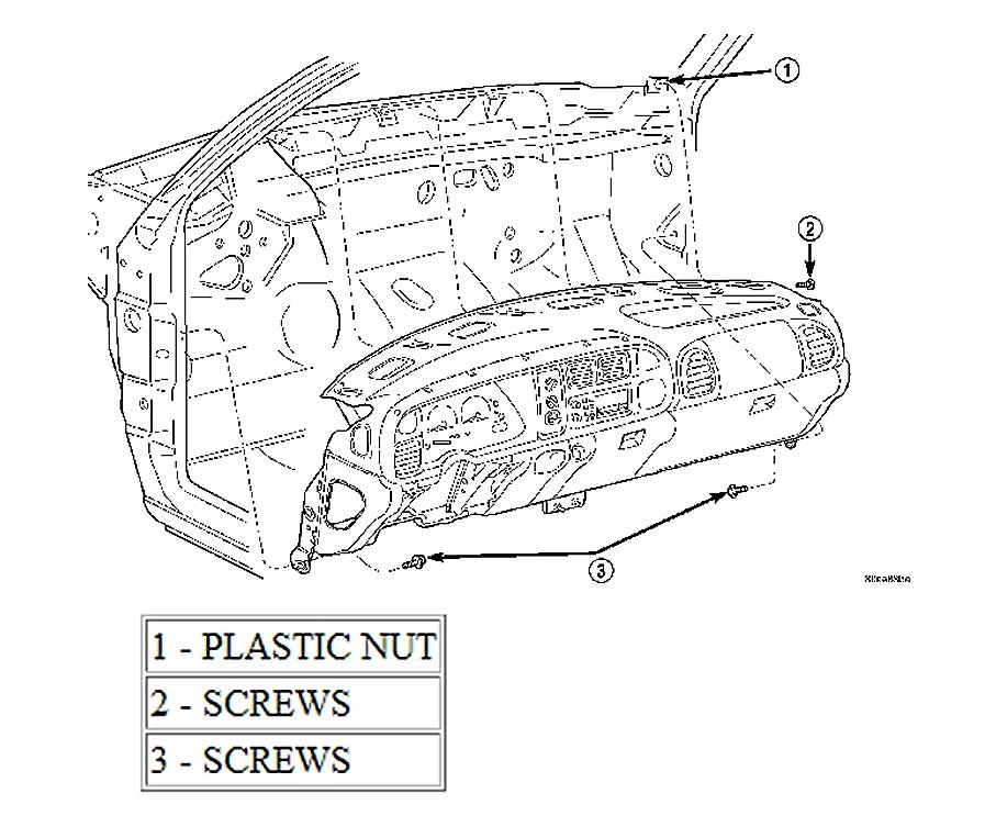
11. Loosen the right and left instrument panel cowl side roll-down bracket screws about 13 mm (0.50 inch).
12. Remove the five screws that secure the top of the instrument panel to the top of the dash panel, removing the center screw last.
13. Roll down the instrument panel and install a temporary hook in the center hole on top of the instrument panel. Secure the other end of the hook to the center hole in the top of the dash panel. The hook should support the instrument panel in its rolled down position about 46 cm (18 inches) from the dash panel.
14. With the instrument panel supported in the roll-down position, disconnect the instrument panel wire harness connectors from the heater-A/C housing wire harness connectors.
15. With the aid of an assistant, remove the temporary hook and life the instrument panel assembly off of the roll-down bracket screws and remove it from the vehicle.
______________________________________
2001 Dodge or Ram Truck RAM 1500 Truck 4WD V8-5.9L VIN Z LDC
Installation
Vehicle Body and Frame Interior Moulding / Trim Dashboard / Instrument Panel Service and Repair Removal and Replacement Instrument Panel Assembly Installation
INSTALLATION
INSTRUMENT PANEL ASSEMBLY
Installation
WARNING: On vehicles equipped with airbags, disable the airbag system before attempting any steering wheel, steering column, seat belt tensioner, or instrument panel component diagnosis or service. Disconnect and isolate the battery negative (ground) cable, then wait two minutes for the airbag system capacitor to discharge before performing further diagnosis or service. This is the only sure way to disable the airbag system. Failure to take the proper precautions could result in accidental airbag deployment and possible personal injury.
pic 2
1. With the aid of an assistant, load the instrument panel assembly onto the roll-down bracket screws on the cowl side inner panels in the vehicle. Install a temporary hook in the center hole on top of the instrument panel. Secure the other end of the hook to the center hole in the top of the dash panel. The hook should support the instrument panel in its rolled down position about 46 cm (18 inches) from the dash panel.
2. With the instrument panel supported in the roll-down position, reconnect the instrument panel wire harness connectors to the heater-A/C housing wire harness connectors.
3. Remove the temporary hook from the instrument panel and roll the instrument panel up to its installed position against the dash panel.
4. Install and tighten the five screws that secure the top of the instrument panel to the top of the dash panel. Tighten the screws to 3.2 Nm (28 inch lbs).
5. Tighten the right and left instrument panel cowl side roll-down bracket screws. Tighten the screws to 11.9 Nm (105 inch lbs).
6. From under the driver side of the instrument panel, reconnect the two halves of the radio antenna coaxial cable connector.
7. From under the driver side of the instrument panel, perform following:
a. Engage the park brake release handle linkage rod from the park brake mechanism on the left cowl side inner panel. See: Parking Brake Pedal > Procedures
b. Reconnect the instrument panel wire harness connector from the park brake switch on the park brake mechanism.
c. Reconnect the three connectors (one from the body wire harness, and two from the headlamp and dash wire harness) from the three connector receptacles located closest to the dash panel on the back of the Junction Block (JB).
d. Reconnect the headlamp and dash wire harness to instrument panel wire harness bulkhead connector and tighten the screw in the center of the connector. Tighten the screw to 3.5 Nm (31 inch lbs).
e. Reconnect the instrument panel wire harness to door wire harness connector located directly below the instrument panel wire harness to headlamp and dash wire harness bulkhead connector.
f. If the vehicle is equipped with the Infinity sound system option, Reconnect the infinity wire harness connector from the instrument panel wire harness connector that is secured to the outboard side of the instrument panel wire harness to headlamp and dash wire harness bulkhead connector.
g. Reconnect the instrument panel wire harness connector from the stop lamp switch.
h. Reconnect the heater-A/C housing vacuum harness connector from the heater-A/C control vacuum harness connector located near the left end of the heater-A/C housing.
8. Reinstall the steering column into the vehicle. Be certain that the steering wheel was locked and secured from rotation to prevent the loss of clockspring centering. See: Steering Column > Procedures
9. If the vehicle is so equipped, reconnect the overdrive lockout switch pigtail wire connector to the instrument panel wire harness connector near the instrument panel lower reinforcement.
10. Reconnect the clockspring pigtail wire connector to the instrument panel wire harness connector at the instrument panel lower reinforcement.
11. Position the inside hood latch release handle to the instrument panel lower reinforcement.
12. Install and tighten the two screws that secure the inside hood latch release handle to the instrument panel lower reinforcement. Tighten the screw to 2.8 Nm (25 inch lbs).
13. Reinstall the steering column opening cover onto the instrument panel. See: Dashboard / Instrument Panel > Removal and Replacement
14. Reinstall the trim onto the left and right cowl side inner panels. See: Dashboard / Instrument Panel > Removal and Replacement
15. Reinstall the Airbag Control Module (ACM) and bracket onto the floor panel transmission tunnel. See: Air Bag Control Module > Procedures
16. Reconnect the battery negative cable.
________________________________________
Let me know if this helps.
Take care,
Joe
Images (Click to enlarge)
Jun 29, 2019 at 7:47 PM