Instrument panel cluster not working after removal of rodent nest?

Tiny
PANDABEL
  • MEMBER
  • 2003 CHEVROLET SILVERADO
  • 5.3L
  • V8
  • 4WD
  • AUTOMATIC
  • 130,000 MILES
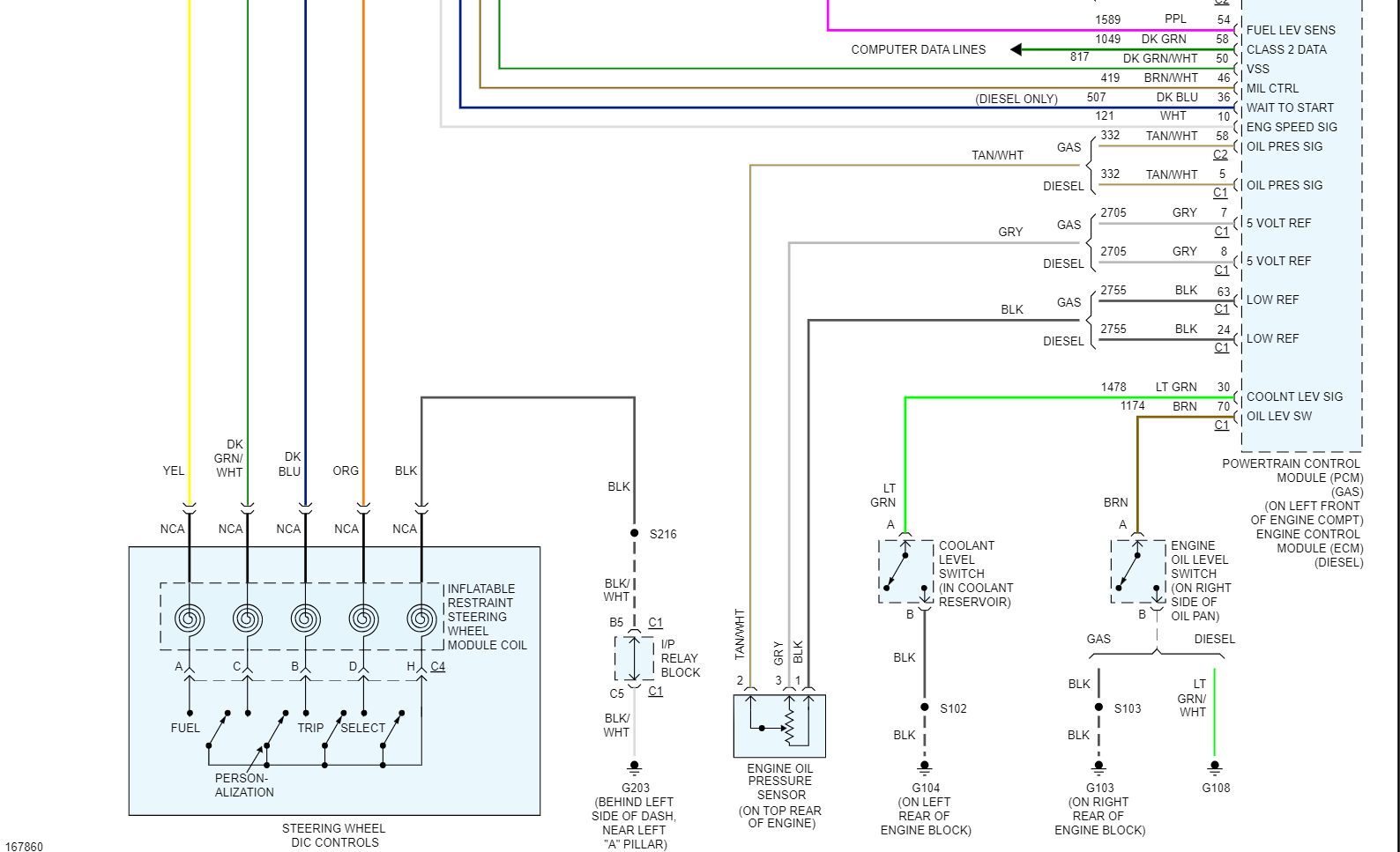
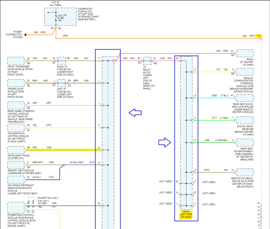
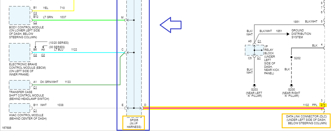
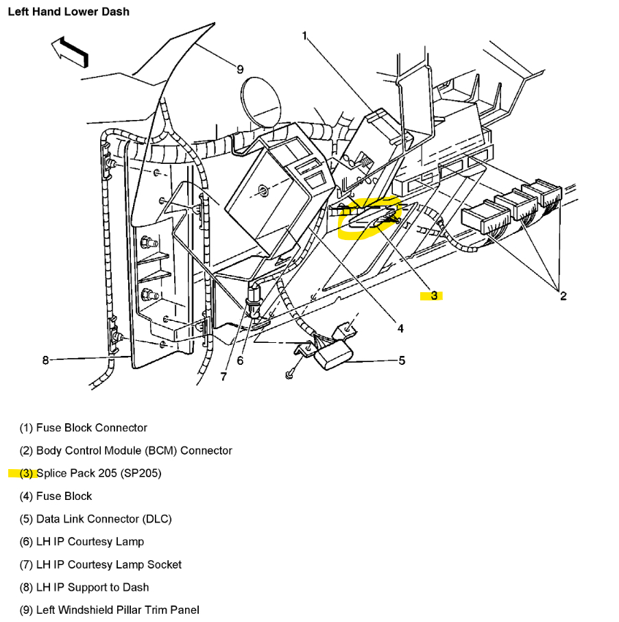
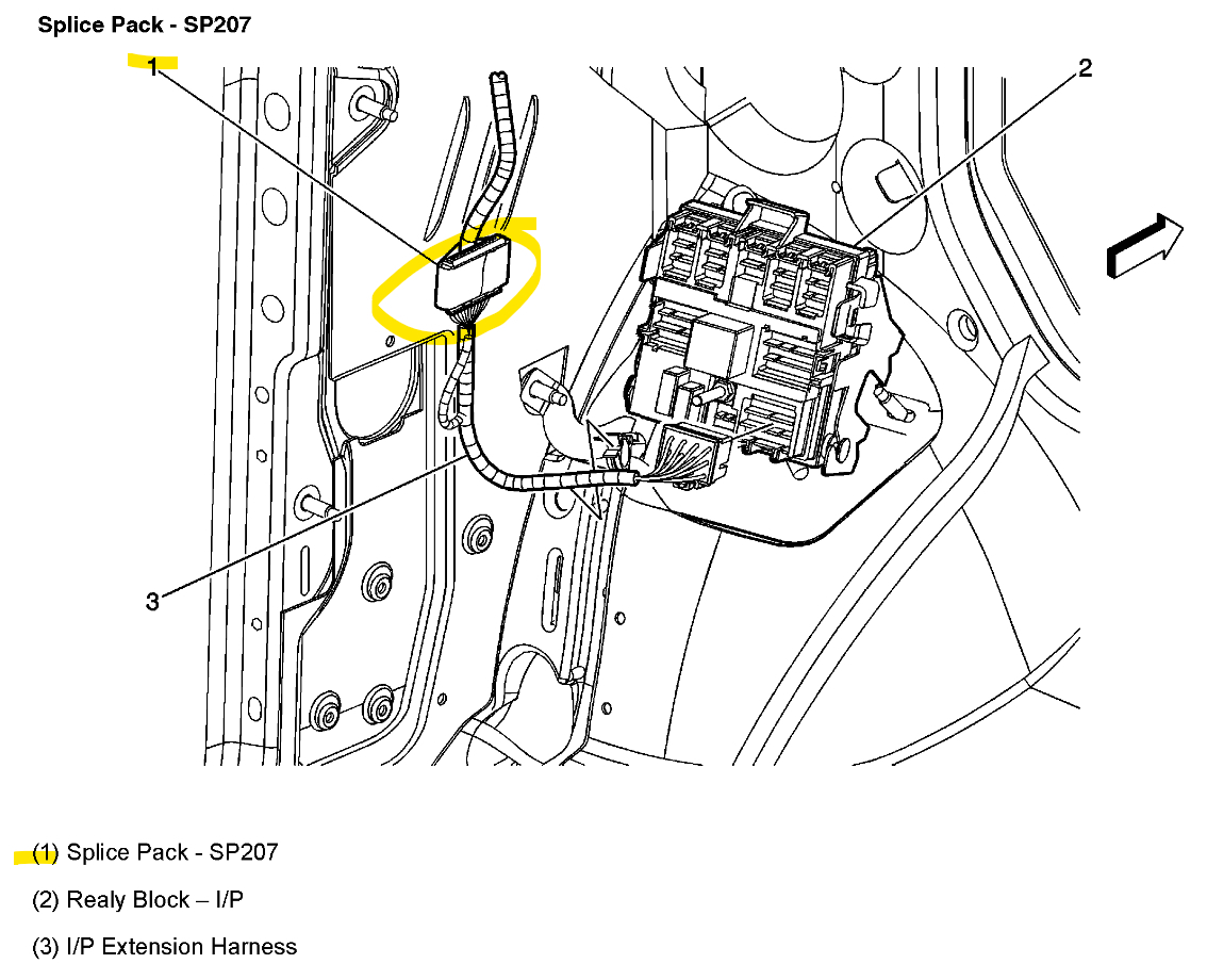
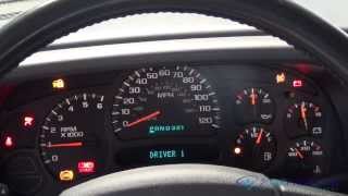
I went to start my truck after it sat idle for three weeks. Would not start and discovered a pine straw nest on the driver’s side up against the power distribution box on the firewall. Charged the battery and it started but no gauges or lights came on, on the dash except check engine light. My mechanic moved the power distribution box around a little and the dash light up and the gauges worked. The next day it still cranked but no dash lights except the check engine light and no gauges were working. (Before all of this happened, I had a dim PRNDL light. When the dash worked for one day after the mechanic the PRNDL display was totally black. I don’t know if this is important, just noticed the difference.) My mechanic wants to have the cluster rebuilt and I am okay with that, but it does seem to account for any problems attributable to the rodent. Could the rodent have caused a short that disabled the IPC? Is there a ground wire that could be loose? It seems wiggling the power distribution box indicates a wiring issue of power or ground. Fuses are all good. Thanks for any help.
Sunday, July 16th, 2023 AT 12:51 PM

4 Replies

Tiny
PANDABEL
  • MEMBER
  • 3 POSTS
But it does not seem to account for any problems attributable to the rodent.
Was this
answer
helpful?
Yes
No
Sunday, July 16th, 2023 AT 1:37 PM
Tiny
AL514
  • MECHANIC
  • 4,119 POSTS
Hello, there are 2 power feeds to the IPC from the engine compartment fuse block. And when it comes to rodent damage almost anything is possible. They like to chew on the wires because of the chemicals in the wiring insulation. Did your mechanic try to communicate with the Cluster via a scan tool. There should be communication to it, it's on the data Bus network in the vehicle. I'd try that and check the powers and grounds to the Cluster before replacing it. What if he plugs in a new Cluster or rebuilt and it either shorts out again or does nothing. Changing out modules should be the last step after diagnosing the circuits first. And you are correct, if a wiggle test brought the cluster back to life there is a wiring issue somewhere. If there was a whole nest, then the rodent could have chewed wires anywhere. I'll post the fuses and diagrams for the Cluster so you can check them.

Diagrams 1 and 2 go together, top and bottom, same with 3 and 4. The 1st diagram has the 2 power feeds and fuses, you'll have to check which fuses you have in the fuse panel. They are both labelled a little different per model. The Grounds that go directly to the Cluster are on the 2nd diagram, Grounds G200 and G203.

https://www.2carpros.com/articles/how-to-check-a-car-fuse

https://www.2carpros.com/articles/how-to-use-a-test-light-circuit-tester
Was this
answer
helpful?
Yes
No
Monday, July 17th, 2023 AT 11:43 AM
Tiny
PANDABEL
  • MEMBER
  • 3 POSTS
Thank you so much for this excellent information. I have learned a lot and have reviewed this information with my mechanic, returned the truck to him and am awaiting the results of his work. I will post again when it is fixed.
Was this
answer
helpful?
Yes
No
Tuesday, July 18th, 2023 AT 12:51 PM
Tiny
AL514
  • MECHANIC
  • 4,119 POSTS
Okay, if you have any other questions just post them here. You might take a look at the connectors on the power distribution panel in the engine compartment, if that's what he did the wiggle test on, this is an older vehicle, so pin fitment and connectors issues will be a concern as well. And just so you know how GM's data bus networks work. If you print out these 2 diagrams below, top and bottom, you can see in the dark blue rectangles I put in, those are the network splices, where each module hooks into the this one wire GM class 2 serial data line, these splices are a comb like connector. The comb goes into the connector and that's how they are all linked together. There is one (SP205) just right of the Data Link Connector where the scan tool is plugged in. And SP207 looks to be near the relay/fuse panel probably down where your left foot would be. But this is how we would check for any module issues, for example a bad module pulling the network down, at these splice packs you can unplug the comb and check each wire running out to each module. So, at SP205 the grey wire is the network wire running out to the Cluster, and each splice pack runs back to pin #2 of the data Link connector for scan tool communications. The network has a bias or nominal voltage of 7-volts, and each module pulls that 7-volts down to ground to send a signal, so it's a 0 to 7-volt signal on that network. But your mechanic could check to see if the Cluster is communicating on the network on that grey wire. If there's no signal from it, then he could check the back of the Cluster for proper power and ground. GM really made this type of network easy to work with, even though it is only a 1 wire network, it really easy to divide the network up to see what's happening. I know this sounds a little technical, but it's not that bad. You could even check YouTube for videos on GM class 2 serial data line and see technicians checking it, and what the splice packs look like. And sorry for the long post.
Was this
answer
helpful?
Yes
No
Tuesday, July 18th, 2023 AT 1:40 PM

Please login or register to post a reply.

Sponsored links