I attached the procedure and pictures below for you.
Roy
REMOVAL
1. DISCONNECT CABLE FROM NEGATIVE BATTERY TERMINAL
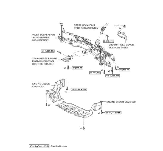
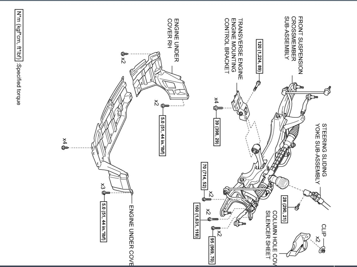
2. REMOVE COLUMN HOLE COVER SILENCER SHEET
3. REMOVE STEERING SLIDING YOKE SUB-ASSEMBLY
4. REMOVE FRONT WHEELS
5. REMOVE ENGINE UNDER COVER LH
6. REMOVE ENGINE UNDER COVER RH
7. DRAIN TRANSAXLE OIL
(a) Remove the filler plug and the gasket.
(b) Remove the drain plug and the gasket, and then drain the manual transaxle oil.
(c) Install a new gasket and the drain plug.
Torque: 39 N*m (400 kgf*cm, 29 ft.*lbf)
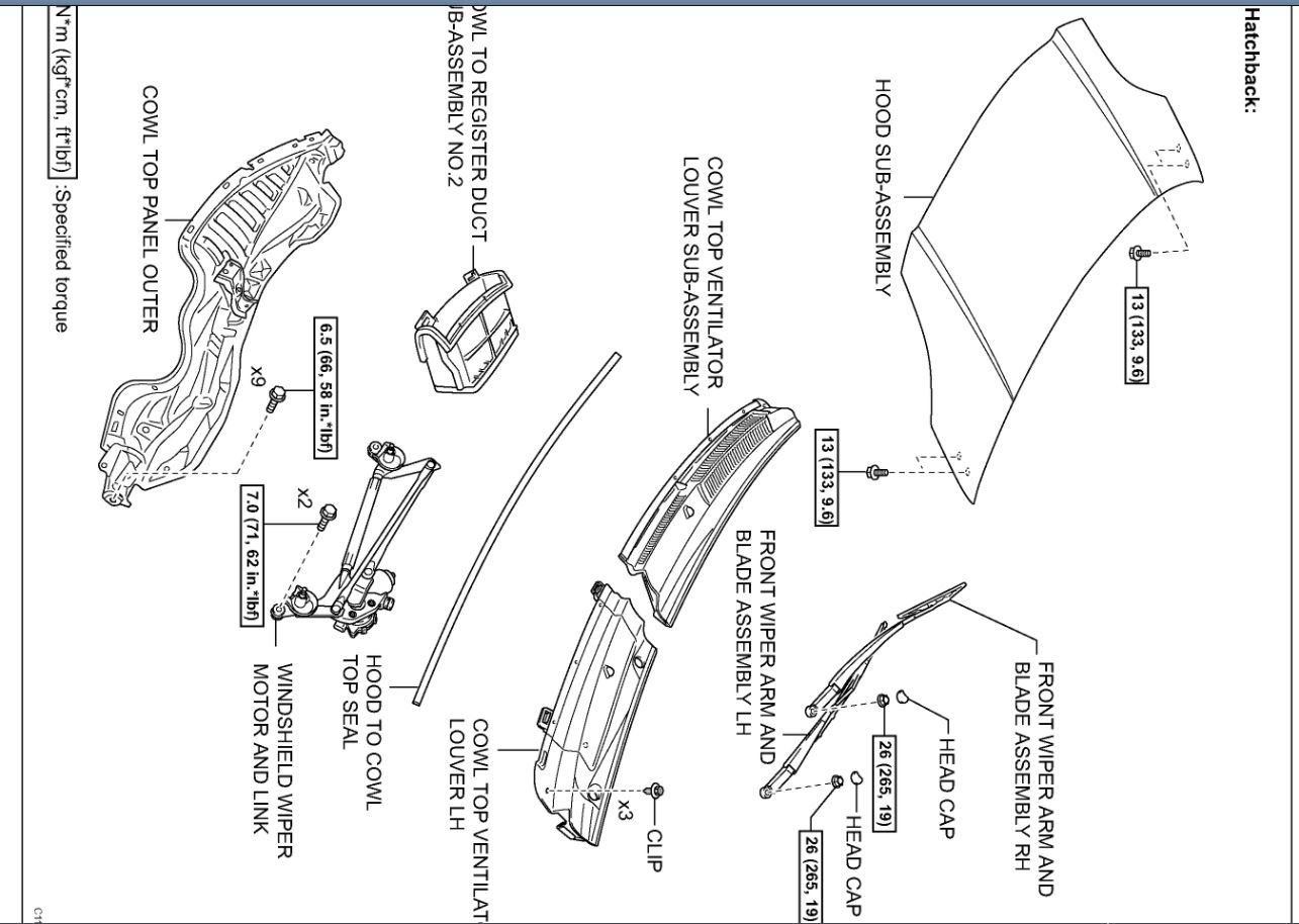
8. REMOVE HOOD SUB-ASSEMBLY
9. REMOVE FRONT WIPER ARM AND BLADE ASSEMBLY LH
10. REMOVE FRONT WIPER ARM AND BLADE ASSEMBLY RH
11. REMOVE HOOD TO COWL TOP SEAL
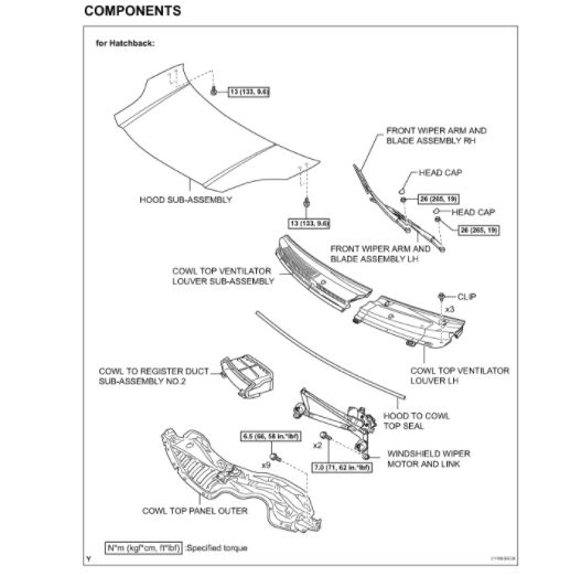
12. REMOVE COWL TOP VENTILATOR LOUVER SUB-ASSEMBLY (for Hatchback)
13. REMOVE COWL TOP VENTILATOR LOUVER LH (for Hatchback)
14. REMOVE WINDSHIELD WIPER MOTOR AND LINK (for Hatchback)
15. REMOVE COWL TO REGISTER DUCT SUB-ASSEMBLY NO.2 (for Hatchback)
16. REMOVE COWL TOP PANEL OUTER (for Hatchback)
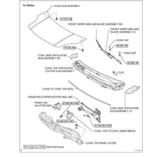
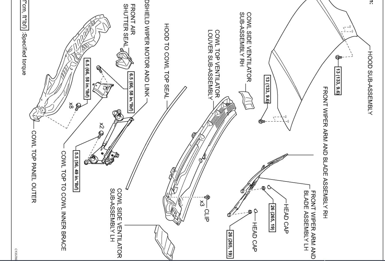
17. REMOVE COWL SIDE VENTILATOR SUB-ASSEMBLY LH (for Sedan)
18. REMOVE COWL SIDE VENTILATOR SUB-ASSEMBLY RH (for Sedan)
19. REMOVE COWL TOP VENTILATOR LOUVER SUB-ASSEMBLY (for Sedan)
20. REMOVE WINDSHIELD WIPER MOTOR AND LINK (for Sedan)
21. REMOVE FRONT AIR SHUTTER SEAL (for Sedan)
22. REMOVE COWL TOP PANEL OUTER (for Sedan)
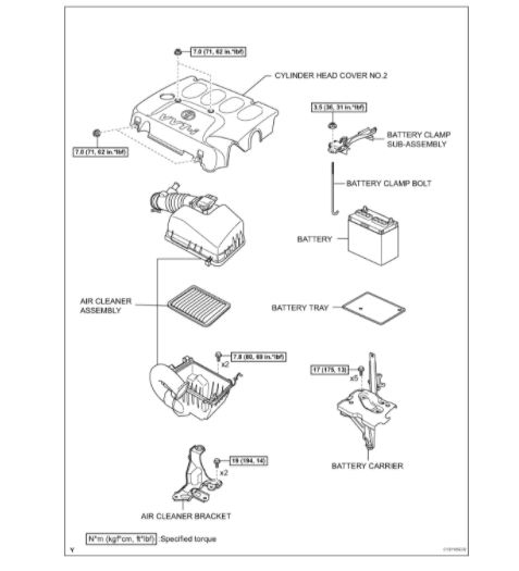
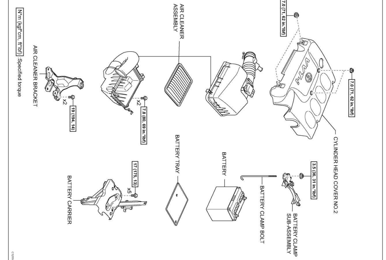
23. REMOVE CYLINDER HEAD COVER NO.2
24. REMOVE AIR CLEANER ASSEMBLY
25. REMOVE AIR CLEANER BRACKET
(a) Remove the 2 bolts and the air cleaner bracket.
26. REMOVE BATTERY CLAMP SUB-ASSEMBLY
27. REMOVE BATTERY
28. REMOVE BATTERY TRAY
imageOpen In New TabZoom/Print
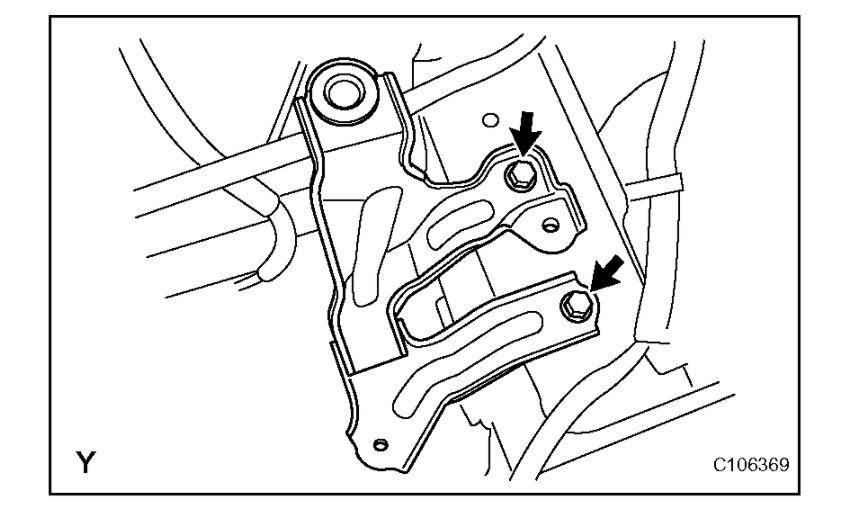
29. REMOVE BATTERY CARRIER
(a) Remove the 5 bolts and the battery carrier.
imageOpen In New TabZoom/Print
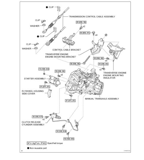
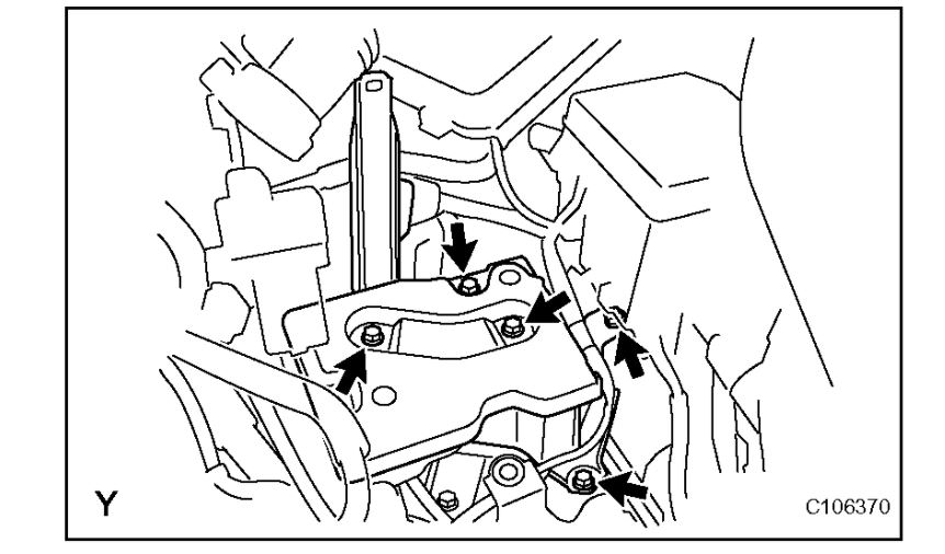
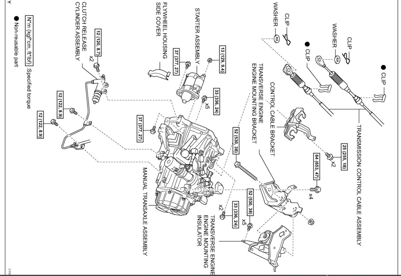
30. SEPARATE CLUTCH RELEASE CYLINDER ASSEMBLY
(a) Remove the 4 bolts, then separate the clutch release cylinder.
HINT: Suspend the clutch release cylinder with a piece of rope so as not to overload the clutch pipe.
imageOpen In New TabZoom/Print
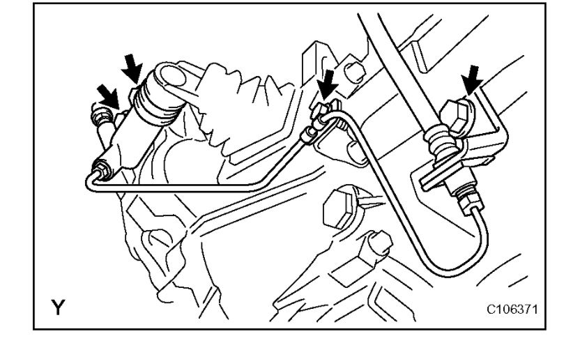
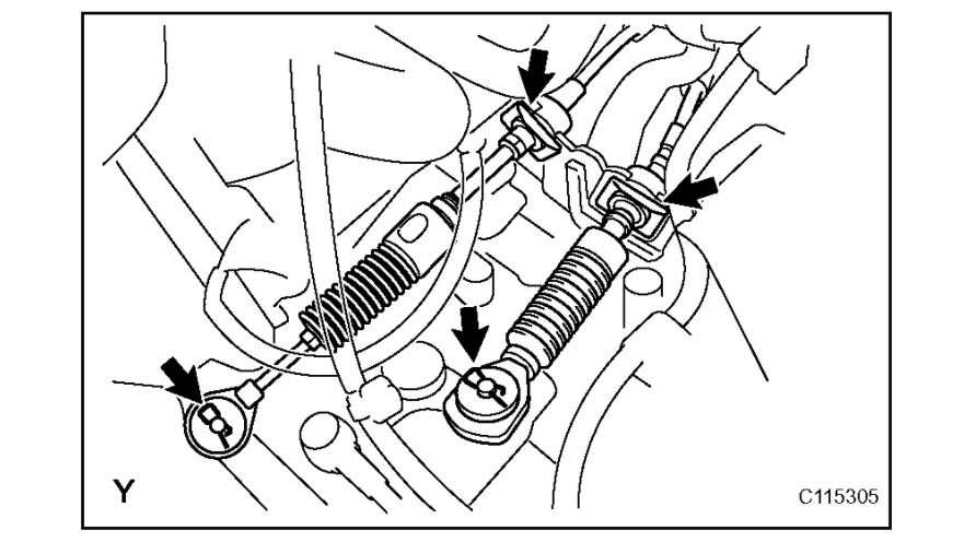
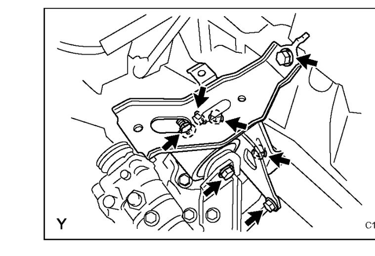
31. SEPARATE TRANSMISSION CONTROL CABLE ASSEMBLY
(a) Remove the 2 clips and the 2 washers, and disconnect the 2 cables from the transaxle.
(b) Remove the 2 clips and disconnect the 2 cables from the control cable bracket.
imageOpen In New TabZoom/Print
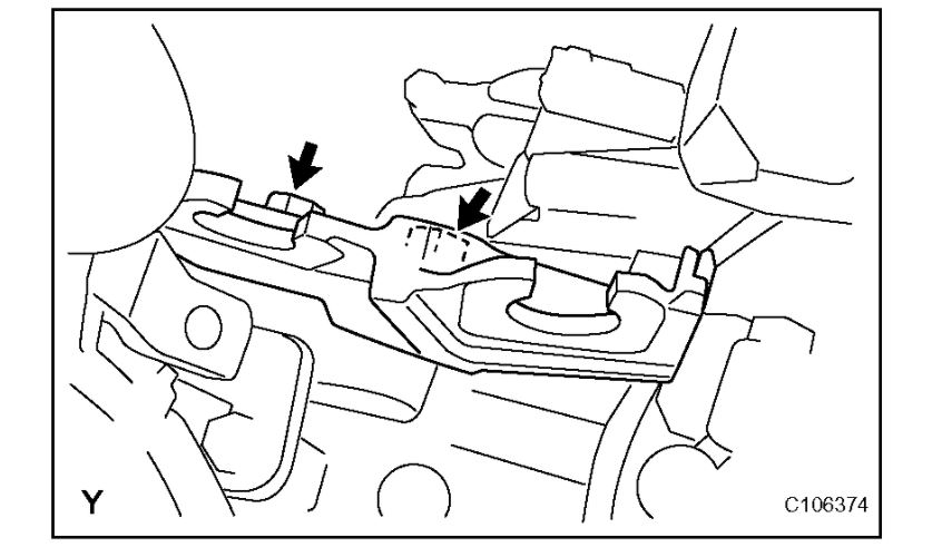
32. REMOVE CONTROL CABLE BRACKET
(a) Remove the 2 bolts and the control cable bracket.
imageOpen In New TabZoom/Print
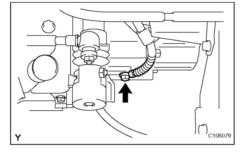
33. DISCONNECT WIRE HARNESS
(a) Remove the bolt, then disconnect the wire harness.
34. DISCONNECT CONNECTOR
(a) Disconnect the back-up light switch connector.
35. REMOVE STARTER ASSEMBLY
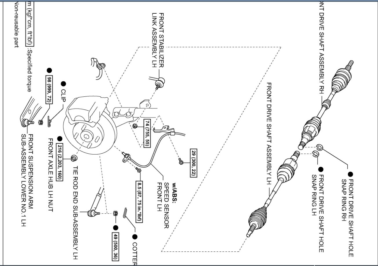
36. REMOVE FRONT AXLE HUB LH NUT
37. REMOVE FRONT AXLE HUB RH NUT
HINT: The removal procedure for the RH side is the same as that for the LH side.
38. SEPARATE SPEED SENSOR FRONT LH (w/ ABS)
39. SEPARATE SPEED SENSOR FRONT RH (w/ ABS)
HINT: The separation procedure for the RH side is the same as that for the LH side.
40. SEPARATE FRONT SUSPENSION ARM SUB-ASSEMBLY LOWER NO.1 LH
41. SEPARATE FRONT SUSPENSION ARM SUB-ASSEMBLY LOWER NO.1 RH
HINT: The separation procedure for the RH side is the same as that for the LH side.
42. SEPARATE TIE ROD END SUB-ASSEMBLY LH
43. SEPARATE TIE ROD END SUB-ASSEMBLY RH
HINT: The separation procedure for the RH side is the same as that for the LH side.
44. SEPARATE FRONT STABILIZER LINK ASSEMBLY LH
45. SEPARATE FRONT STABILIZER LINK ASSEMBLY RH
HINT: The separation procedure for the RH side is the same as that for the LH side.
46. SEPARATE FRONT AXLE ASSEMBLY LH
47. SEPARATE FRONT AXLE ASSEMBLY RH
HINT: The separation procedure for the RH side is the same as that for the LH side.
48. REMOVE FRONT DRIVE SHAFT ASSEMBLY LH
49. REMOVE FRONT DRIVE SHAFT ASSEMBLY RH
imageOpen In New TabZoom/Print
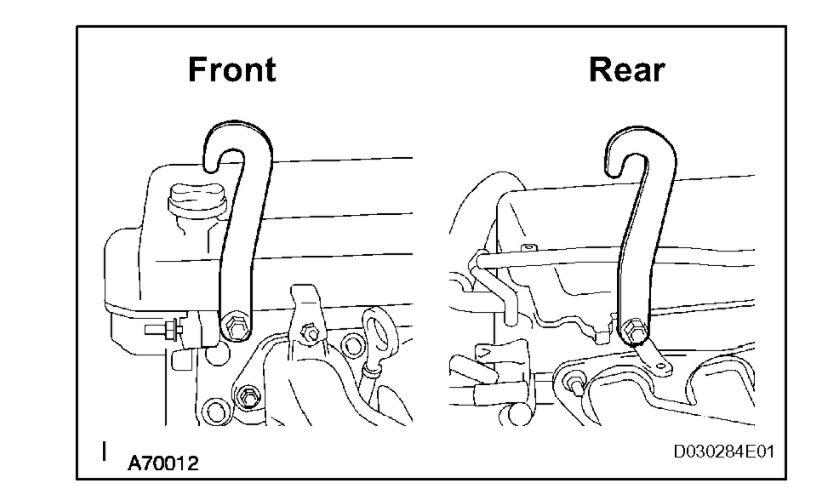
50. SUSPEND ENGINE ASSEMBLY
(a) Install the 2 hangers in the correct direction.
(b) Attach the engine chain hoist to the hangers.
CAUTION: Do not attempt to hang the engine by hooking the chain to any other part.
Parts No.:
Engine Hanger: 12281-21010
Bolt: 91642-81025
Torque: 40 N*m (408 kgf*cm, 29 ft.*lbf)
51. REMOVE FRONT SUSPENSION CROSSMEMBER SUB-ASSEMBLY
imageOpen In New TabZoom/Print
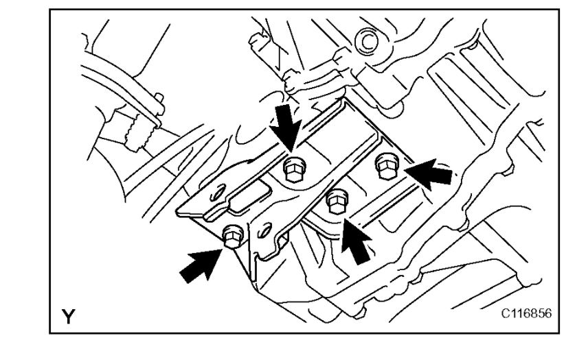
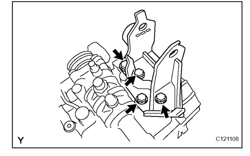
52. REMOVE TRANSVERSE ENGINE ENGINE MOUNTING CONTROL BRACKET
(a) Remove the 4 bolts and the engine mounting control bracket.
53. SUPPORT MANUAL TRANSAXLE ASSEMBLY
imageOpen In New TabZoom/Print
54. REMOVE TRANSVERSE ENGINE ENGINE MOUNTING INSULATOR
(a) Remove the bolt and nut, then separate the engine mounting insulator LH.
(b) Remove the 5 bolts and the engine mounting insulator LH.
imageOpen In New TabZoom/Print
55. REMOVE TRANSVERSE ENGINE ENGINE MOUNTING BRACKET
(a) Remove the 4 bolts and the engine mounting bracket LH.
imageOpen In New TabZoom/Print
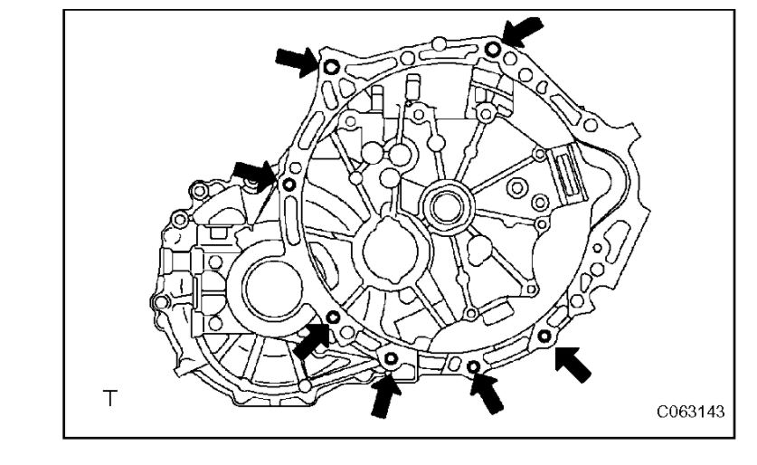
56. REMOVE MANUAL TRANSAXLE ASSEMBLY
(a) Remove the 7 bolts and the manual transaxle.
Images (Click to enlarge)
Mar 23, 2021 at 11:56 AM