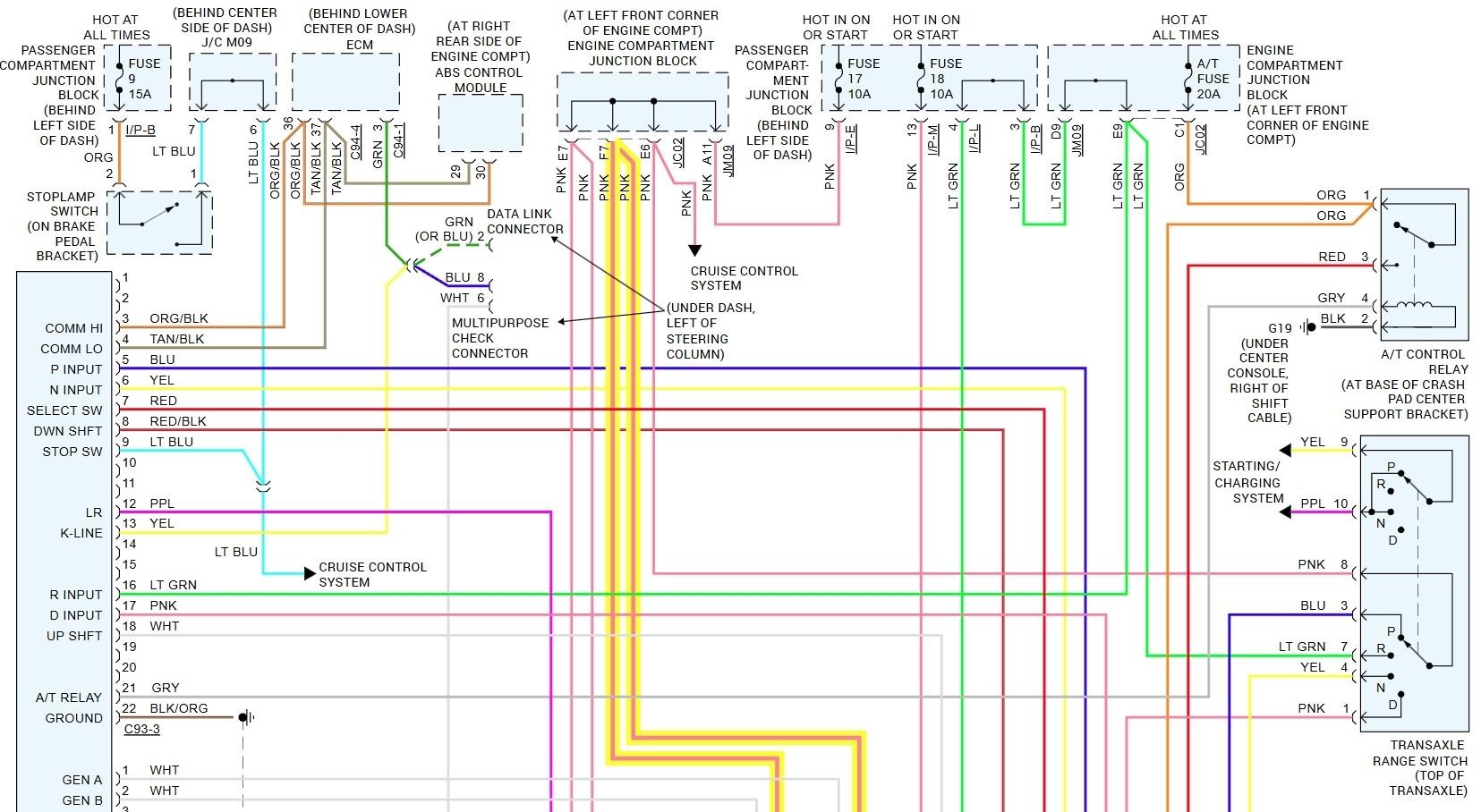
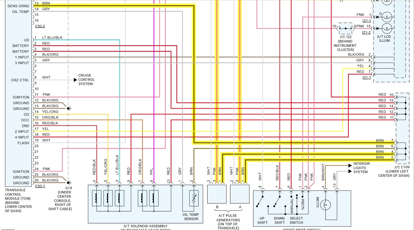
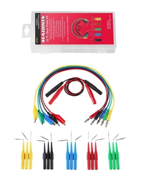
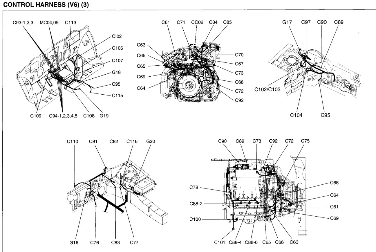
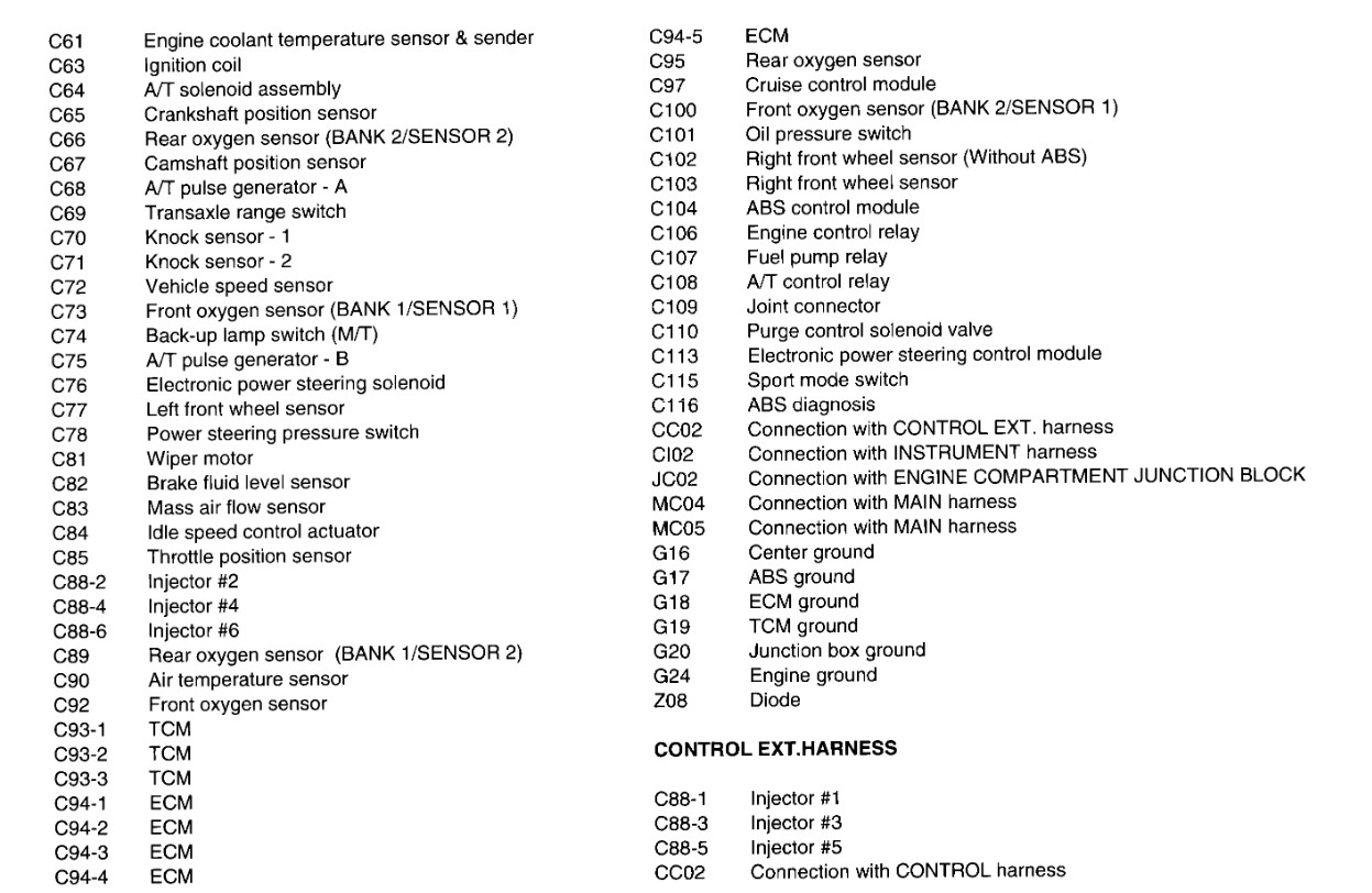
Okay, that could be the harness, the connector or the sensor itself. It's usually an open circuit from either the sensor failure, the connector or a damaged harness. What have you already done? Swapped the sensor? Tested the voltage and ground at the connector itself? For that you should be able to use a meter with the key on and look for battery power on the pink wire in pin 3. Should be a ground through the PCM on the brown wire in pin 1. If those are both there then check for continuity on the white signal wire on pin 2 up to pin 1 in the 93-2 connector on the TCM. There is a TSB about those codes as well. Just covers the testing and a visual inspection of the harness. I would test each of the three wires, then if one of them is bad replace only that wire, replacing the harness (if you could even find a good one) requires far more work. The first step of which is to remove the engine so you can access all of the harness sections. For example if you don't find a ground at pin 1 in the input sensor, it shares that connection with the output sensor, you could simply run a jumper between them, same with the power feed. The signal wire though would be a single wire.
Images (Click to enlarge)
Apr 27, 2025 at 2:51 PM