Welcome to 2CarPros.
I hate to say it, but I feel the entire steering column needs removed. I looked at different exploded views of the column and can see how it can work any other way.
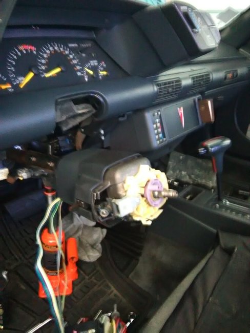
Here are the directions for removing the column. The attached picture correlates with these directions.
________________
Removal
Steering wheel removal for vehicles with redundant steering wheel controls has been revised by service bulletin No. 90-110-9.
1. On 1990-91 models, remove air cleaner.
2. On all models, disconnect battery ground cable, then remove steering wheel as necessary. When removing steering wheel that is equipped with redundant steering wheel controls, insert wheel puller bolts only four to six threads deep to prevent bolts from going all the way through the hub.
3. Remove left hand sound insulator and the trim panel below steering column.
4. Unlock steering column, then push top of intermediate shaft seal down for access to upper intermediate shaft coupling and upper coupling pinch bolt.
5. Rotate intermediate shaft as necessary to remove upper coupling pinch bolt.
6. Disconnect shift indicator cable end and casing from steering column and transaxle shift lever, or park lock cable if equipped with floor shift.
7. Disconnect transaxle shift cable from ball stud on transaxle shift lever, then remove transaxle shift cable casing from steering column bracket by depressing two tabs.
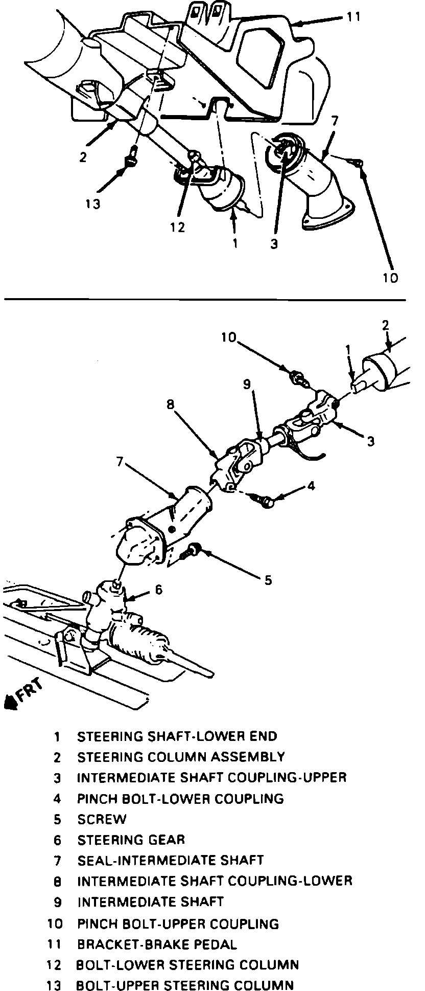
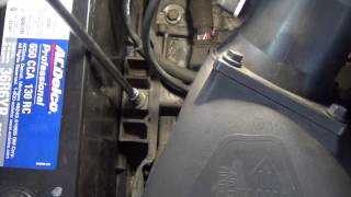
Fig. 27 Steering Column Removal And Installation.
See Picture 1
8. Remove lower steering column attaching bolts, Fig. 27, then the upper steering column attaching bolts, and lower steering column to seat.
9. Disconnect electrical connector by loosening the screw and separating the two halves.
10. Withdraw lower end of steering shaft from upper intermediate shaft coupling and remove column. It may be necessary to spread coupling clamp with a screwdriver to withdraw steering shaft.
Installation
1. Install column back into vehicle and insert lower end of column shaft into upper intermediate shaft coupling.
2. Connect column electrical connector, tightening screw that draws the two halves together.
3. Connect transaxle shift cable and transaxle shift cable casing to column bracket and shift lever ball stud, or park lock cable if equipped with floor shift.
4. Install transaxle shift indicator cable end and casing and connect cable to transaxle shift lever.
5. Loosely install upper and lower steering column attaching bolts, then torque to 18 lb ft
6. Install upper coupling pinch bolt into upper intermediate shaft coupling and torque to 35 lb ft
7. Ensure clearance between lower shaft coupling and steering gear is at least.08 inch, then pull up intermediate shaft seal over lower column until it locks in place.
8. Install trim panel below steering column and the left hand sound insulator.
9. In stall steering wheel, if removed, then connect battery ground cable and confirm proper operation of all steering column components and functions.
10. On 1990-91 models, install air cleaner.
________________________________________
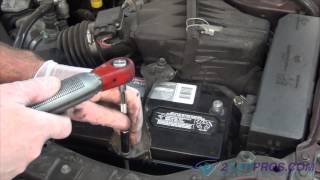
I don't know if you want them, but here are the directions for replacement of the switch specific to your vehicle. I thought I would add them just in case you wanted them. The remaining pictures correlate with these directions.
________________________________________
IGNITION & DIMMER SWITCH
Tilt Wheel Steering Column
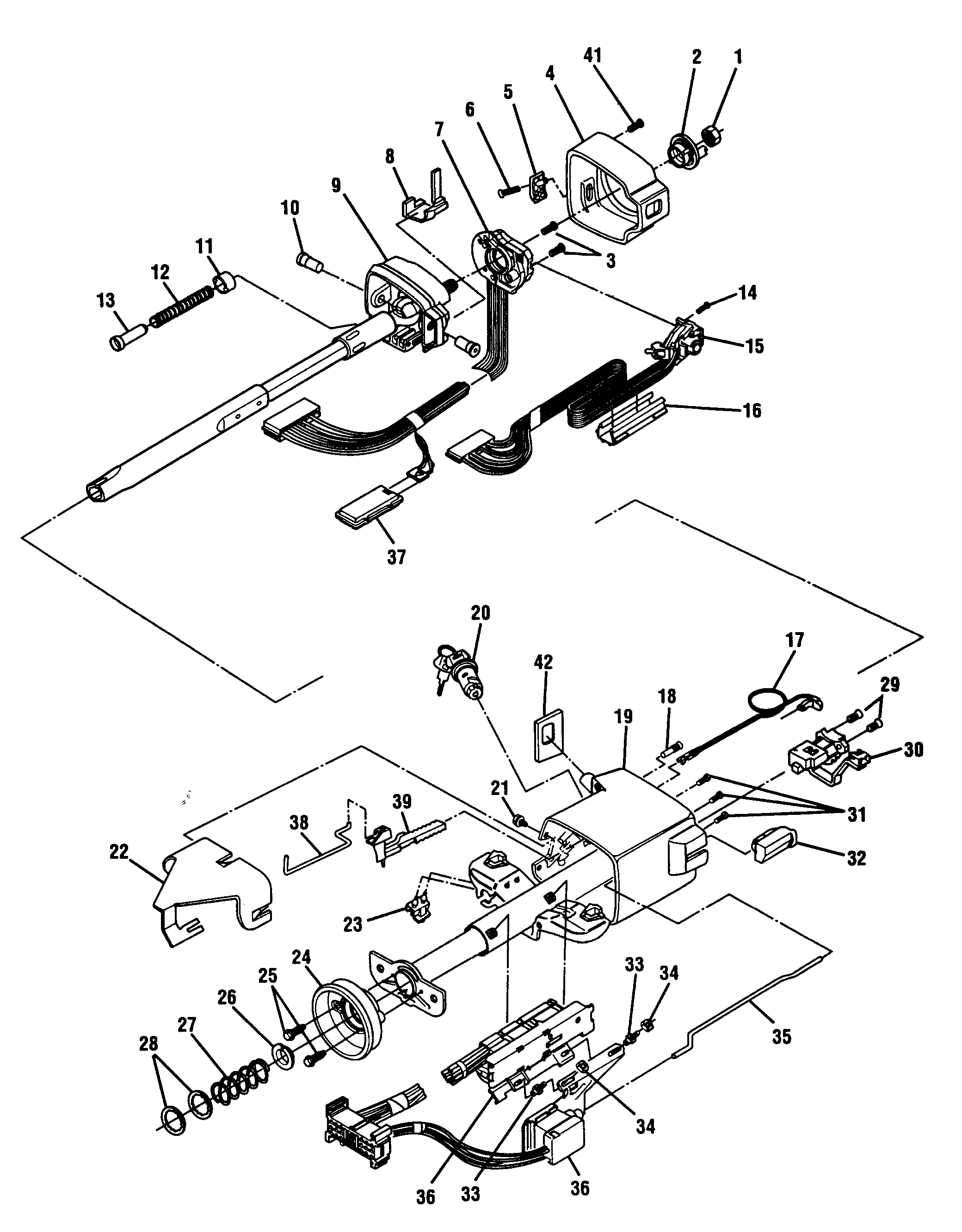
See Picture 2
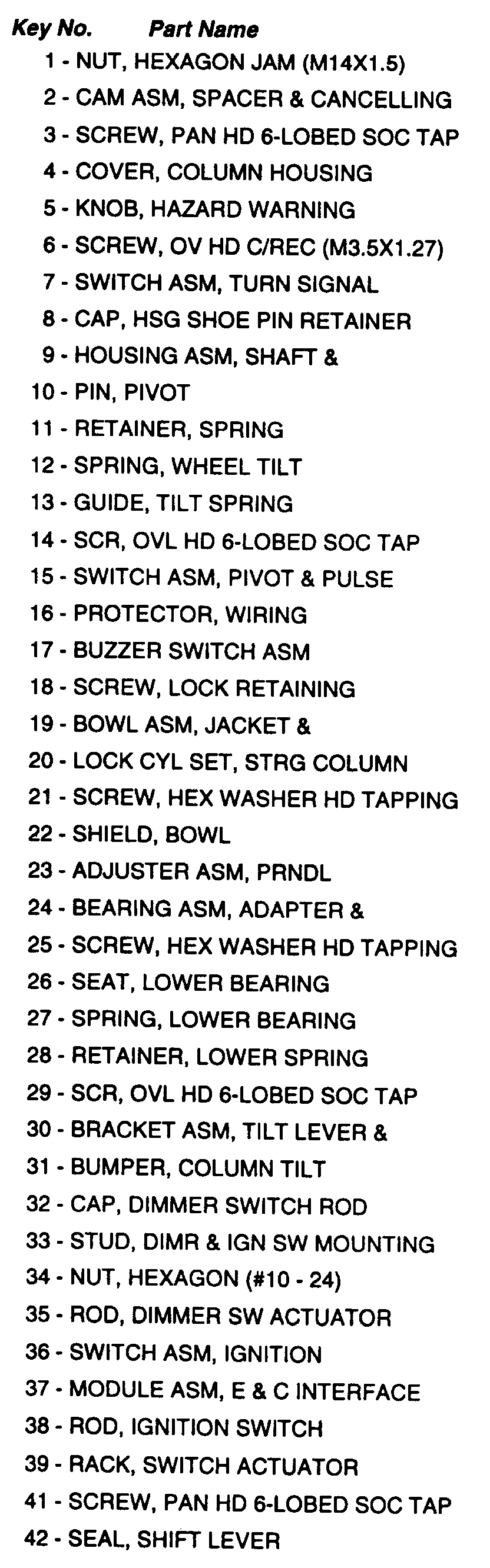
Legend
Picture 3
Remove or Disconnect
1. Place shift lever in "Park" position.
2. Place lock cylinder (20) in "Off-Lock" position.
3. Steering column from car.
4. Turn signal switch connector (7) from ignition and dimmer switch assembly connector (36).
5. Pivot and pulse switch assembly connector (15) from ignition and dimmer switch assembly connector (36).
6. Bowl shield screw (21).
7. Bowl shield nut (34).
8. Bowl shield (22).
9. Dimmer and ignition switch assembly (36) as follows:
- Dimmer switch nut (34).
- Upper mounting stud (33).
- Dimmer switch.
- Lower mounting stud (33).
- Ignition switch from ignition switch actuator rod.
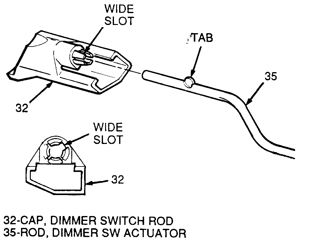
10. Dimmer switch actuator rod (35) from rod cap (32).
Ignition Switch And Actuator Installation
Picture 4
Dimmer Switch Rod Installation
Picture 5
Install or Connect
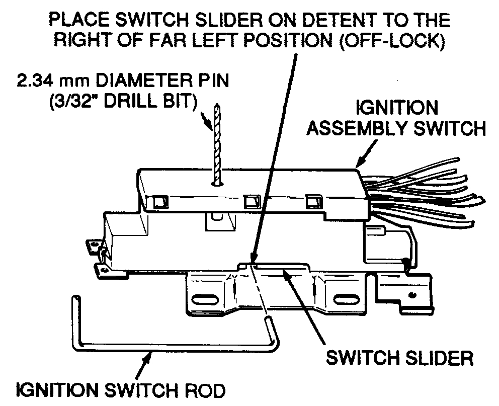
Important: All fasteners in the following steps must be firmly seated before being tightened to specified torque. Lock cylinder set (20) must be in the "Off-Lock" position when installing ignition switch to insure proper switch slider positioning.
1. Place the ignition switch slider in the far left position and move back one detent to the right, "Off-Lock" position.
Important: Insert a 2.34 mm diameter pin (3/32" drill bit) in adjustment hole on ignition switch to hold switch slider in proper position during installation.
2. Ignition switch (36) to switch rod (38).
3. Ignition switch (36) to jacket and howl assembly (19) with lower mounting stud (33) and torque to 4 Nm (35 lb. In.).
4. Remove adjustment tool from ignition switch (36).
5. Dimmer switch actuator rod (35), tab end first, through hole in "IP" bracket and into hole in dimmer switch rod cap (32). Tab on rod (35) must engage wide slot in rod cap (32) and snap in place.
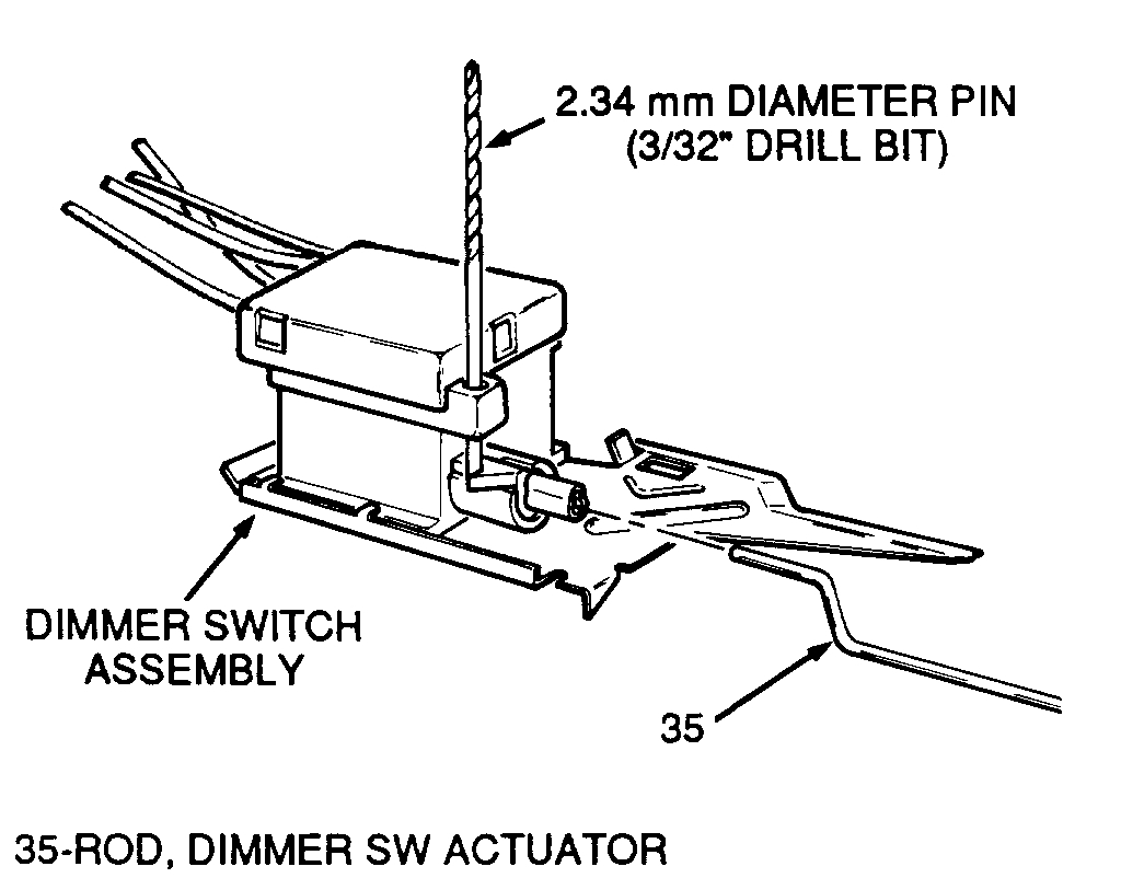
6. Dimmer switch onto actuator rod (35).
7. Dimmer switch assembly on lower mounting stud (33) with dimmer switch nut (34) and upper mounting stud (33). Do not tighten.
Dimmer Switch Adjustment
Picture 6
Important: To adjust dimmer switch, insert a 2.34 mm diameter pin (3/32" drill bit). Push switch against actuator rod (35) to remove all lash.
Tighten: Dimmer switch nut (34) and upper mounting stud (33) to 4 Nm (35 lb. In.).
8. Remove adjustment tool from dimmer switch.
9. Bowl shield (22) to jacket and howl assembly (19) and upper mounting stud (33).
10. Shield screw (21) and torque to 3.4 Nm (30 lb. In.).
11. Bowl shield nut (34) and torque to 4 Nm (35 lb. In.).
12. Turn signal switch connector (7) to ignition and dimmer switch assembly connector (36).
13. Pivot and pulse switch connector (15) to ignition and dimmer switch (36).
14. Steering Column in car.
15. Park lock cable into ignition switch inhibitor and snap in place.
________________________________
Let me know if this helps or if you have other questions.
Take care,
Joe
Images (Click to make bigger)
Friday, April 5th, 2019 AT 8:23 PM