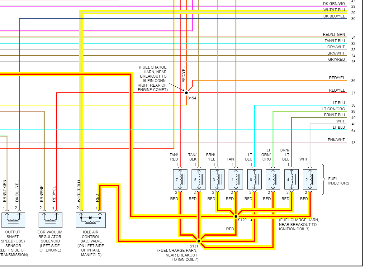
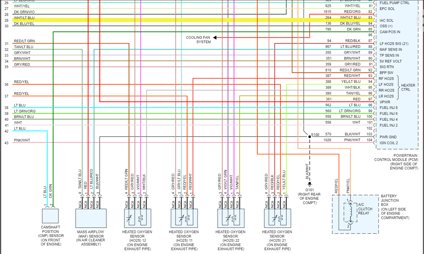
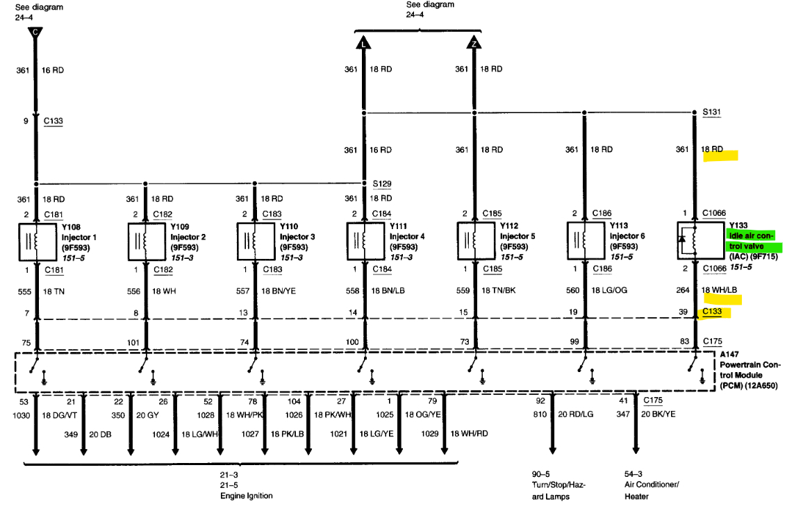
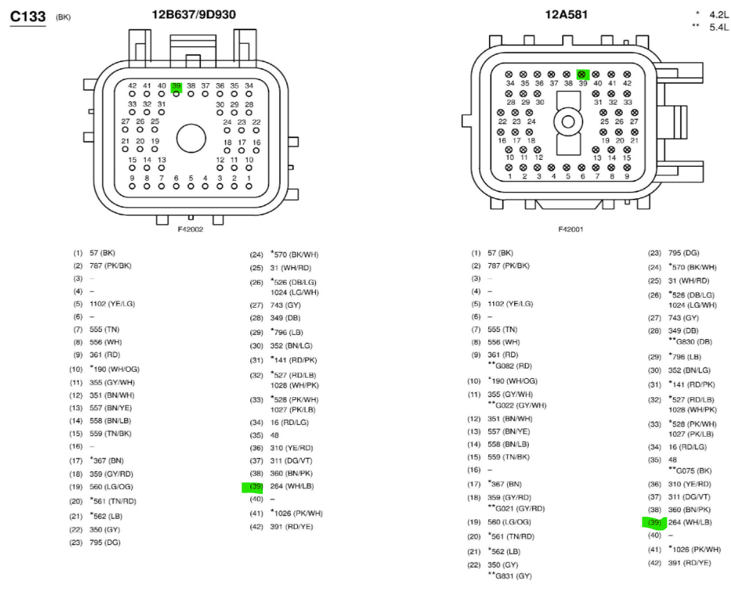
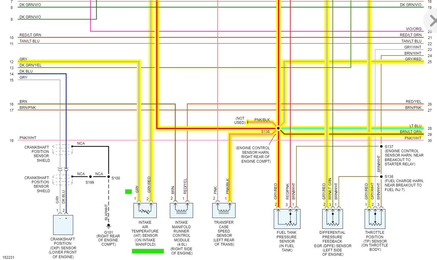
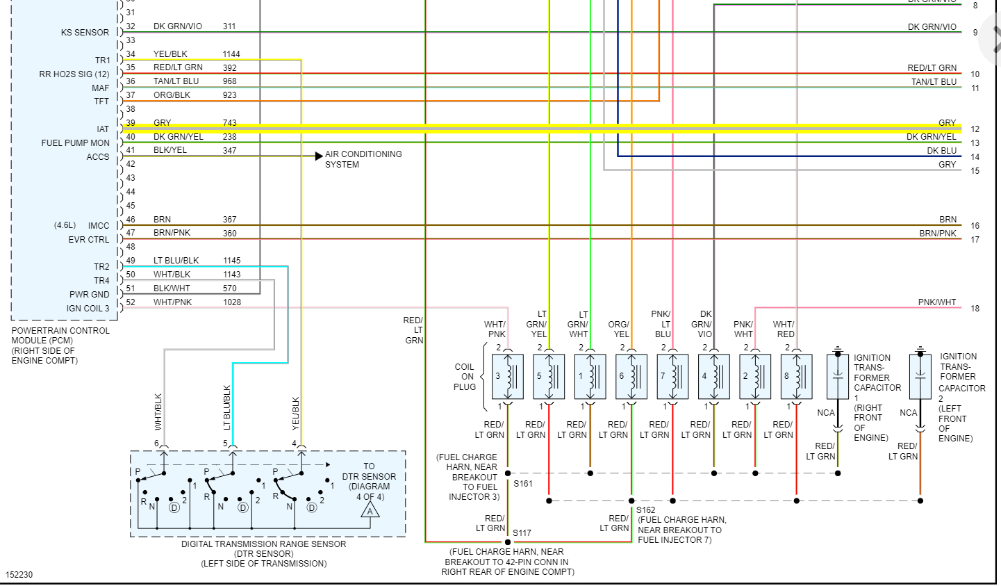
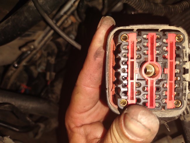
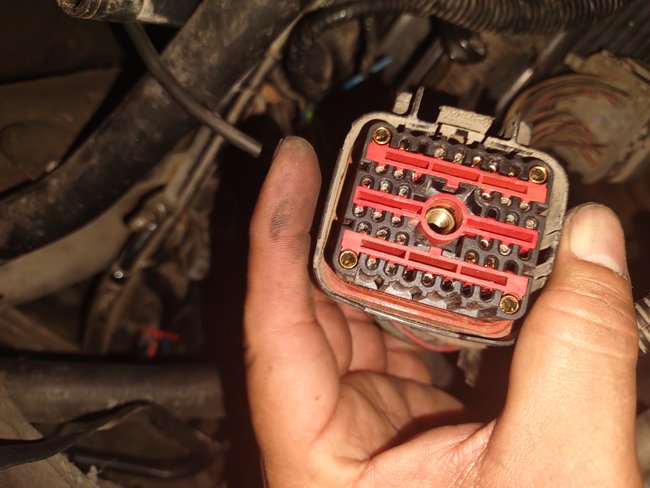
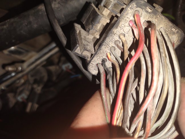
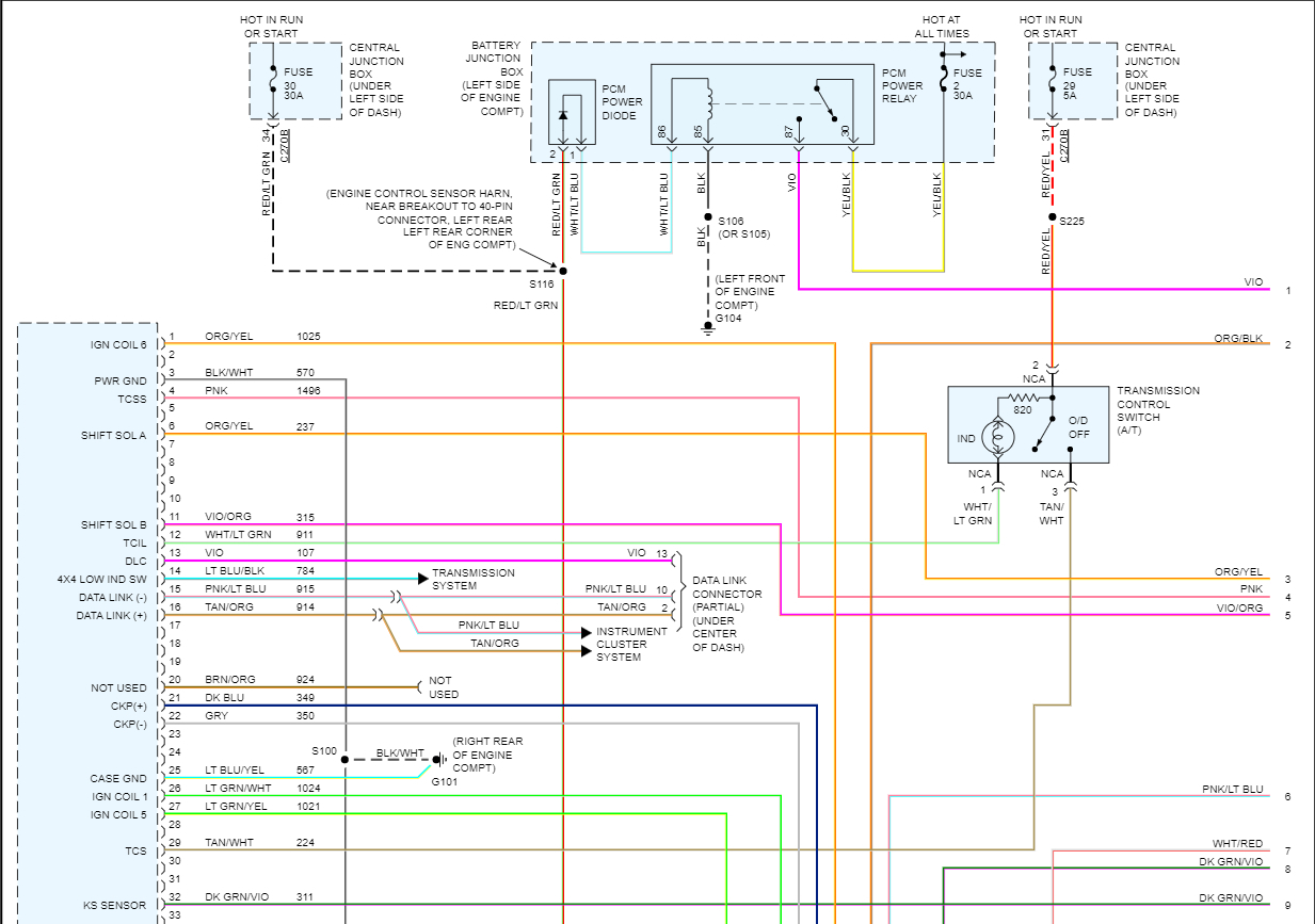
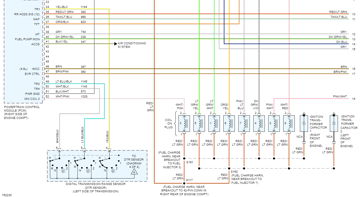
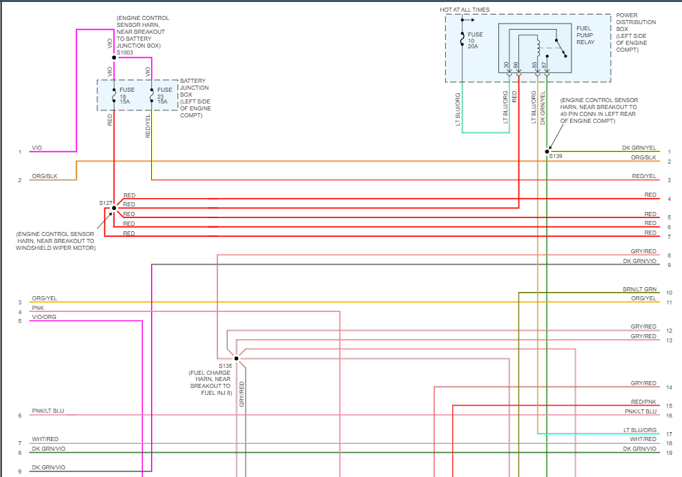
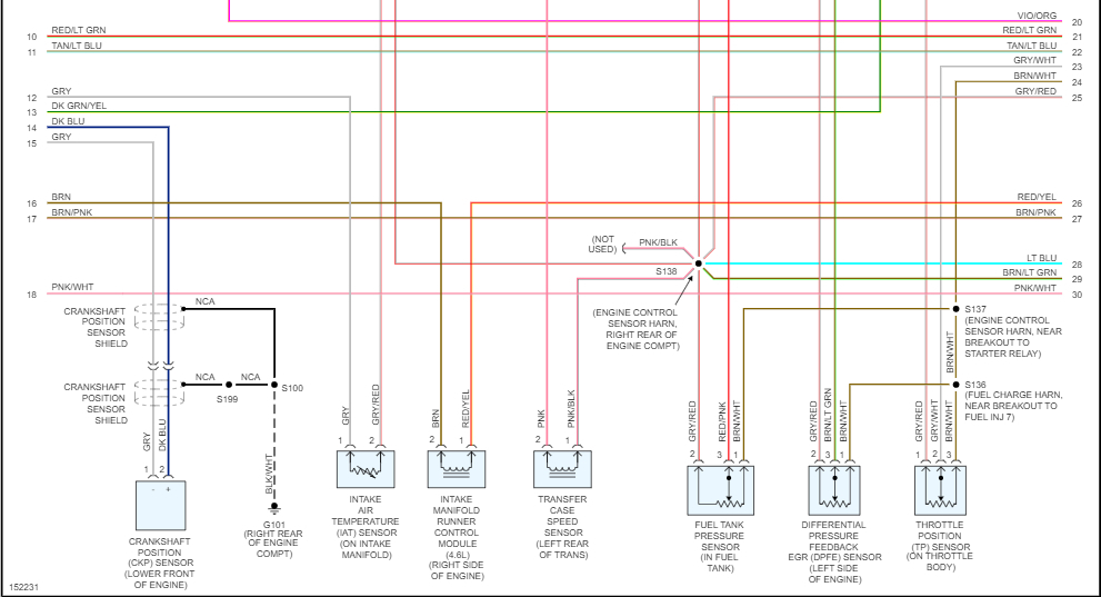
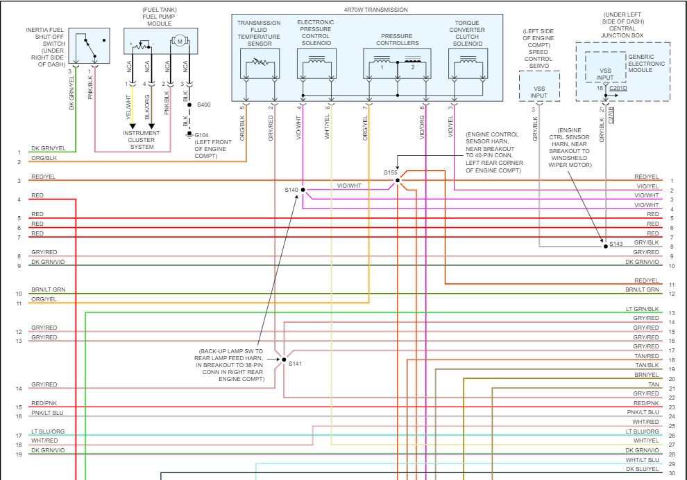
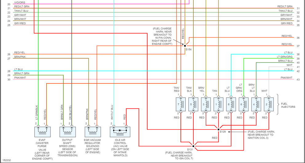
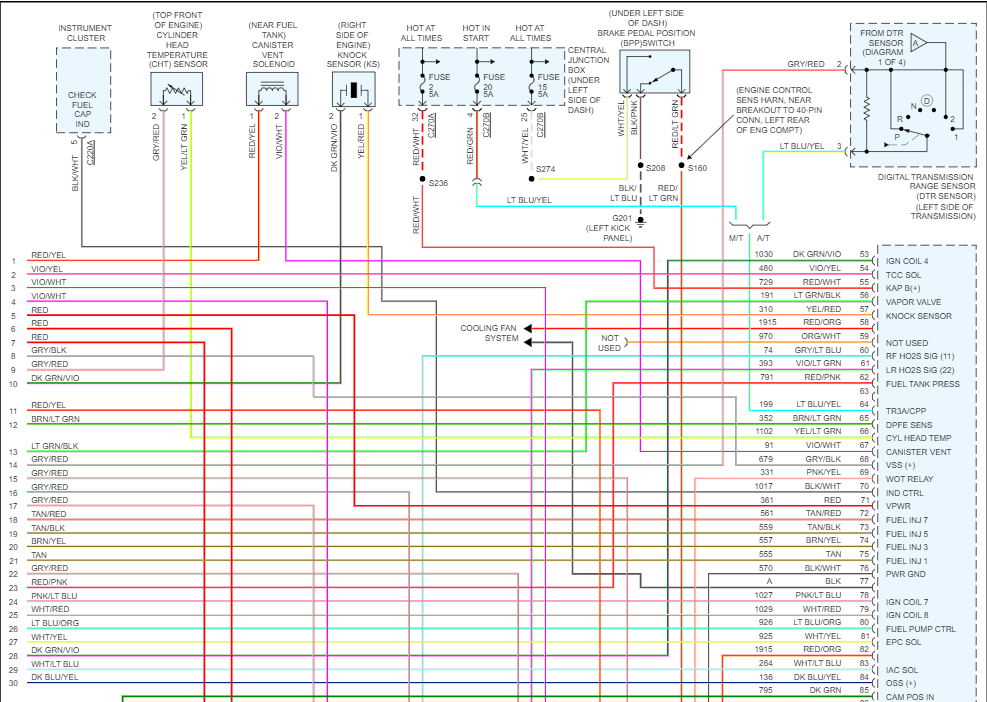
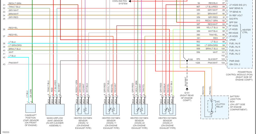
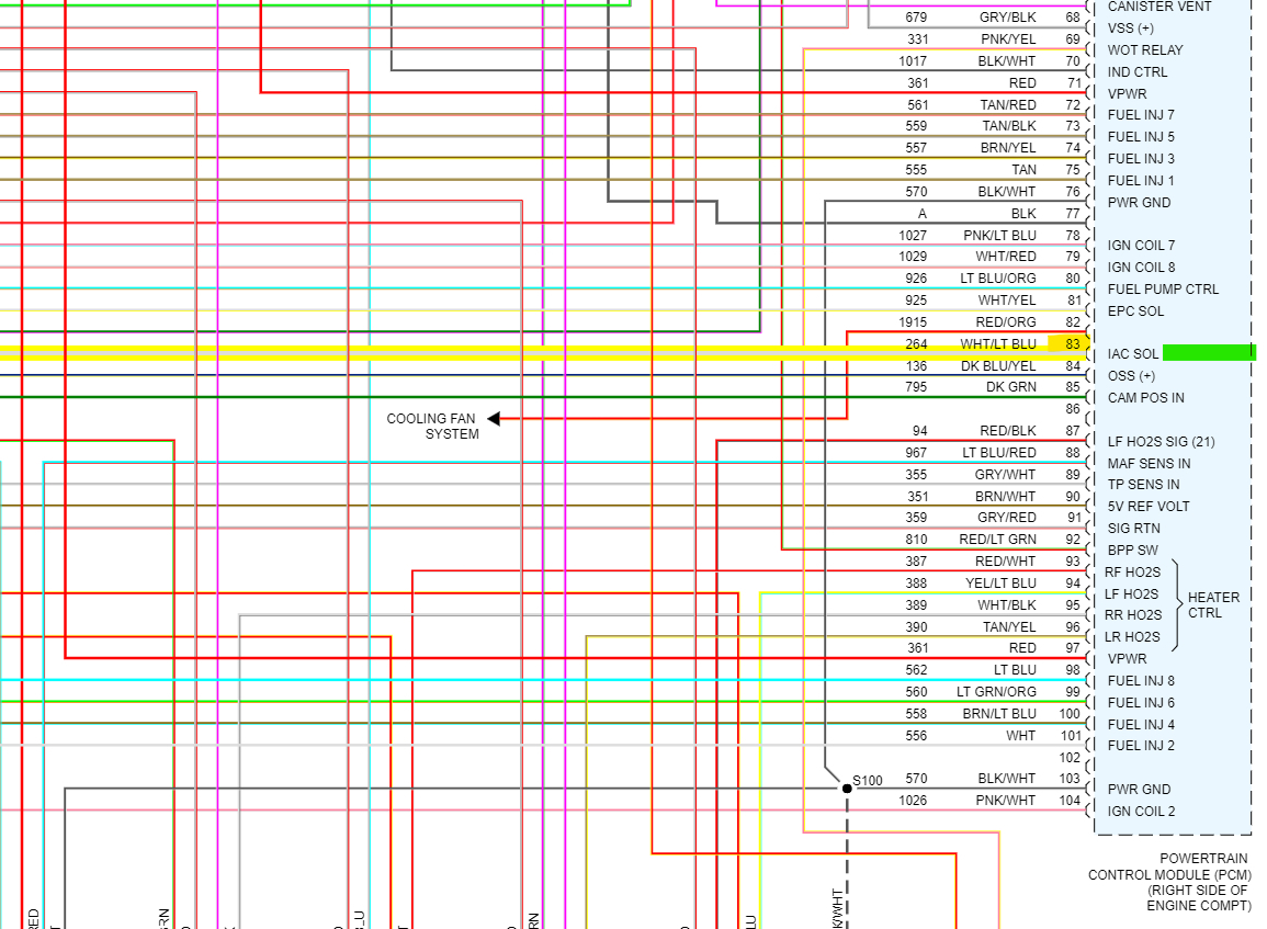
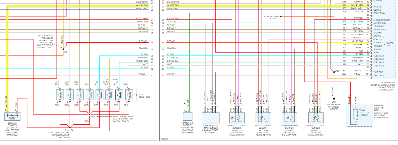
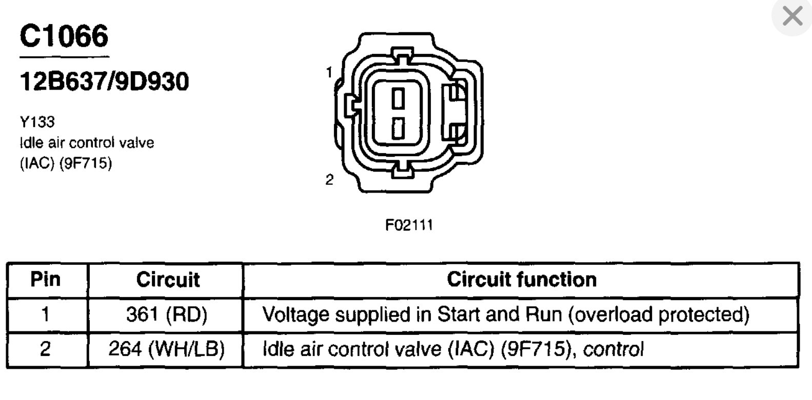
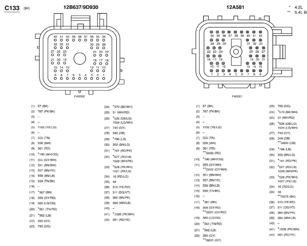
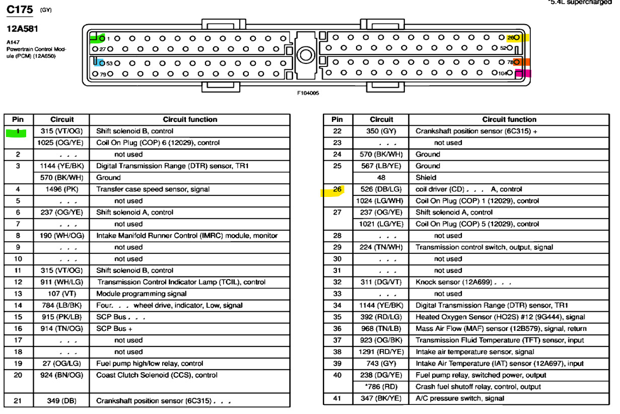
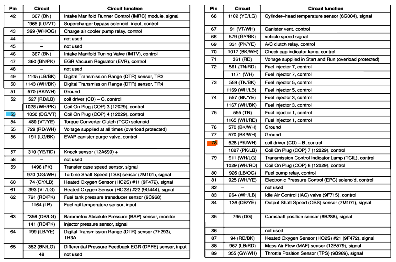
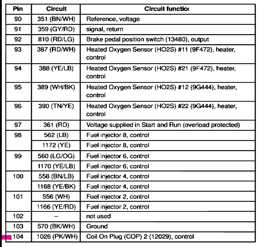
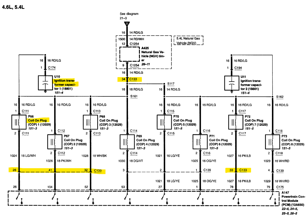
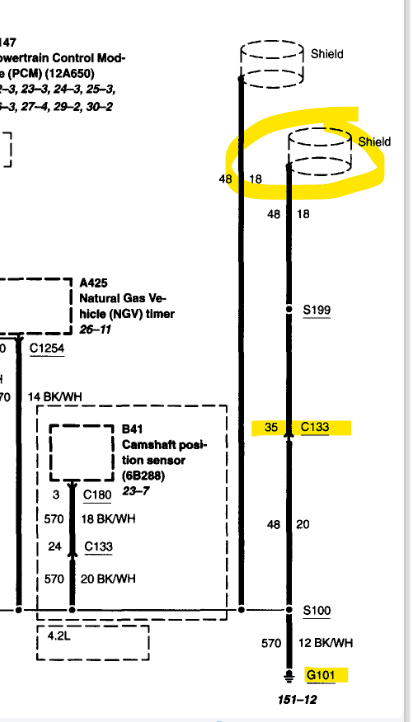
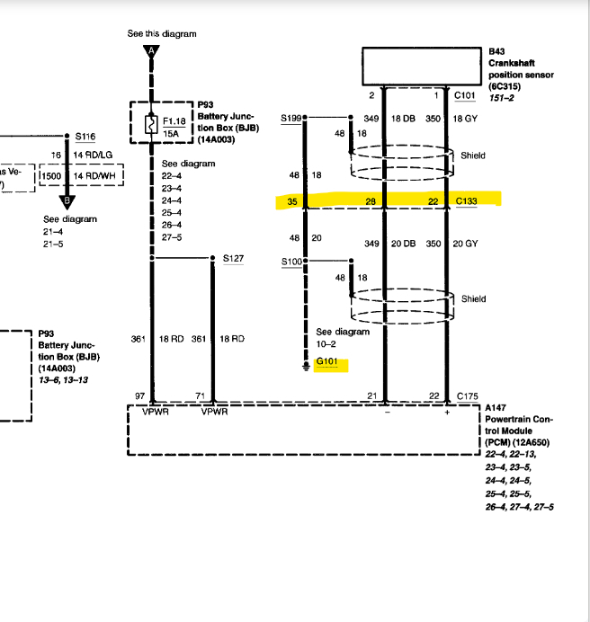
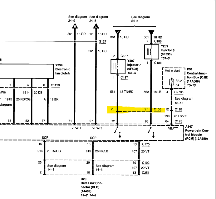
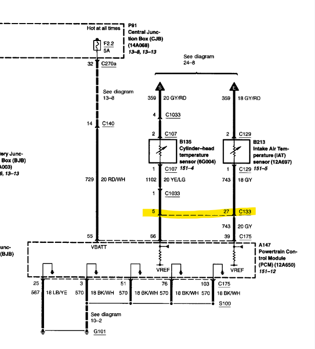
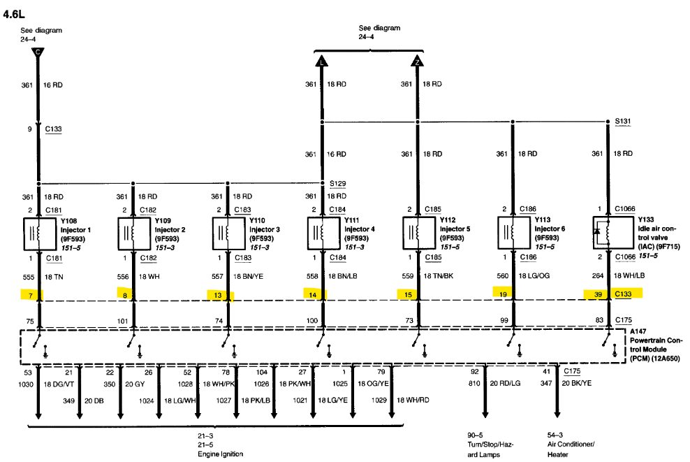
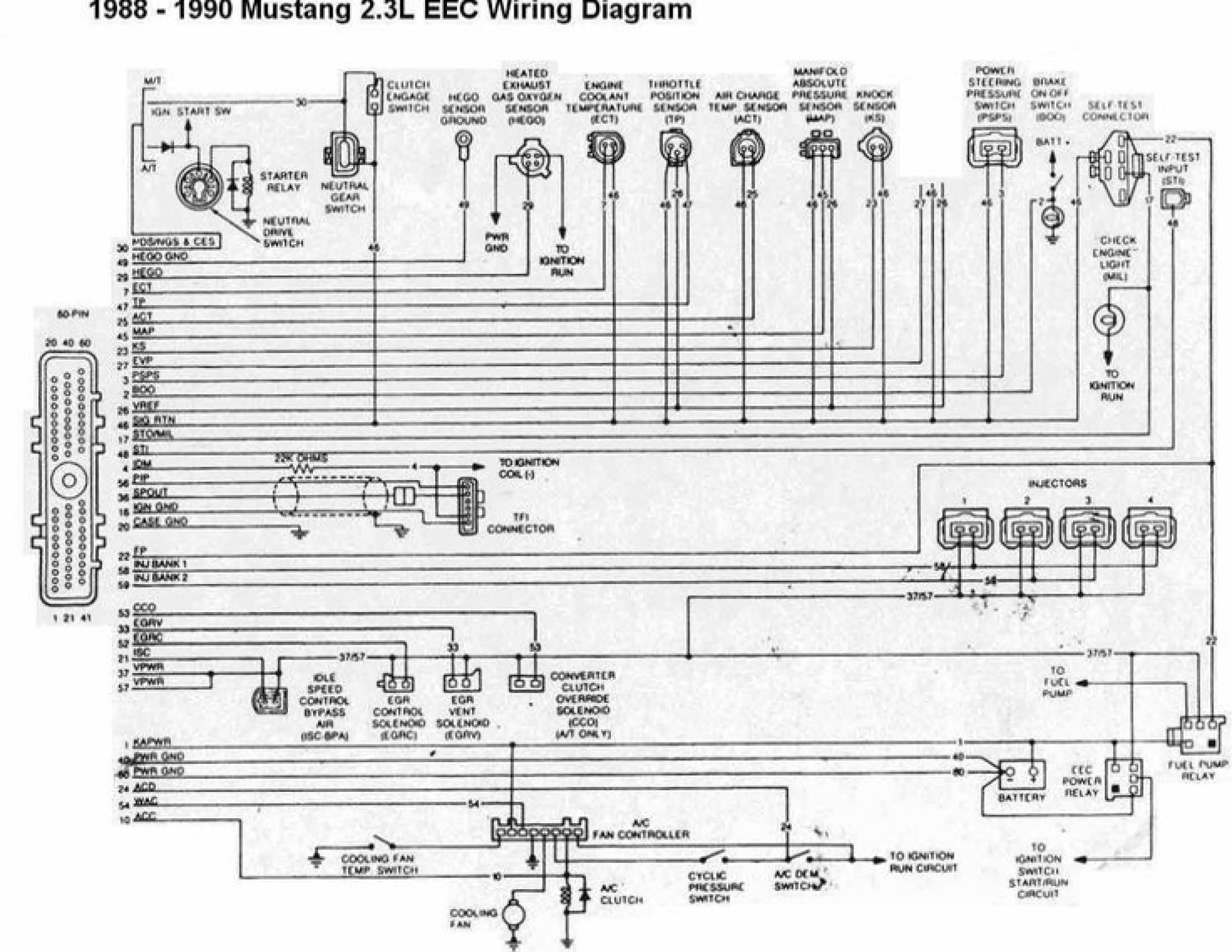
I have no power on the Idle air control valve connector when I turn the key to the on position. I've attached a light Noid and no power. The truck starts but it shuts off. The only way I can keep it running is by keeping the throttle open just a bit. So Iam thinking that since there is no power to the IAC through the connector it's not sending the amount of air coming in so that the motor can supply the correct amount of fuel, so then it shuts off. The other thing I was thinking is the key might have gotten unprogrammed. All this started when I replaced the valve cover gaskets. And in doing so I unplugged the main connectors on the firewall. I've cleaned the throttle body; I've confirmed I got spark and fuel. It just does not stay running and there is no power at the IAC connector. I need a wire diagram for the idle air control valve that looks similar to the picture below so I can trace those wires and see if there is power or continuity. Can someone please help? Thank you! Truck in question is listed above, a XLT crew cab.
Image (Click to enlarge)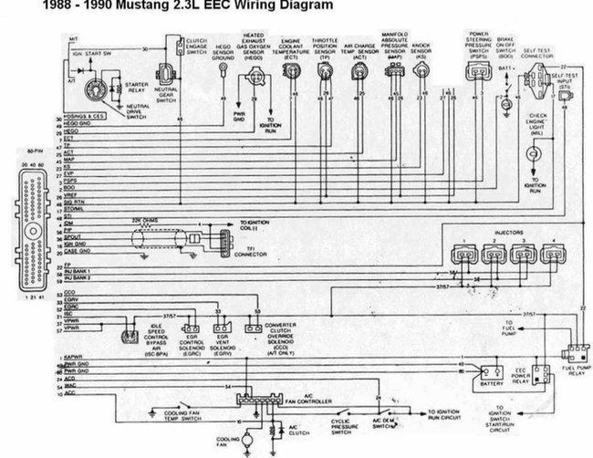
Sep 13, 2022 at 2:17 PM