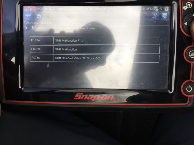
Hi,
If you look at pic 1, it shows location. Here are the directions for removal and replacement. Pic 2 correlates with these directions.
2005 Honda Accord L4-2.4L
Output Shaft (Countershaft) Speed Sensor Replacement
Vehicle Powertrain Management Transmission Control Systems Sensors and Switches - Transmission and Drivetrain Sensors and Switches - A/T Transmission Speed Sensor Service and Repair Procedures Output Shaft (Countershaft) Speed Sensor Replacement
OUTPUT SHAFT (COUNTERSHAFT) SPEED SENSOR REPLACEMENT
Output Shaft (Countershaft) Speed Sensor Replacement
pic 2
1. Disconnect the output shaft (countershaft) speed sensor connector, and remove the output shaft (countershaft) speed sensor.
2. Install the new O-ring (A) on the new output shaft (countershaft) speed sensor (B), then install the output shaft (countershaft) speed sensor in the transmission housing.
3. Check the connector for rust, dirt, or oil, and clean if necessary, then connect the connector securely.
_______________
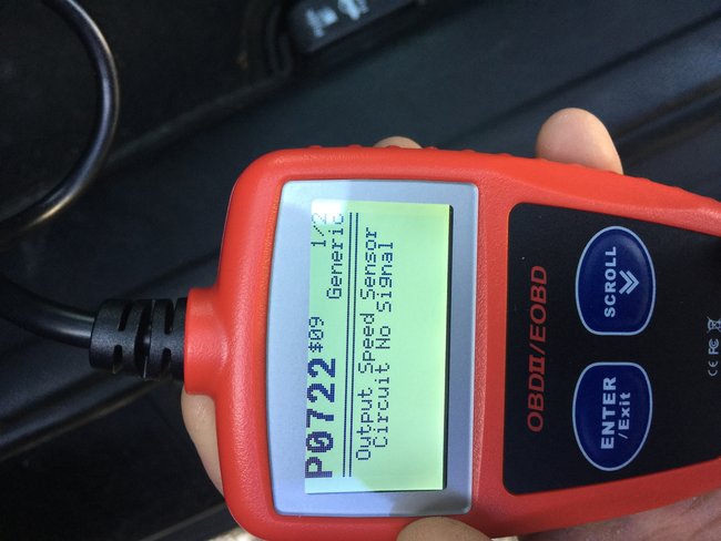
I am going to add the diagnostics for the code you have. It is extensive, but thought I would add it in case you would rather check before replacing the sensor. The remaining pics correlate with these steps.
2005 Honda Accord L4-2.4L
DTC Troubleshooting
Vehicle ALL Diagnostic Trouble Codes ( DTC ) Testing and Inspection P Code Charts P0722 DTC Troubleshooting
DTC TROUBLESHOOTING
DTC P0722: Problem in Output Shaft (Countershaft) Speed Sensor Circuit (No Signal Input)
NOTE:
- Before you troubleshoot, record all freeze data and any on-board snapshot, and review General Troubleshooting Information.
- This code is caused by an electrical circuit problem and cannot be caused by a mechanical problem in the transmission.
1. Turn the ignition switch ON (II).
2. Clear the DTC with the HDS.
3. Check for proper output shaft (countershaft) speed sensor installation.
4. Raise the front of the vehicle, make sure it is securely supported, and allow the front wheels to rotate freely. Or raise the vehicle on a hoist.
5. Start the engine, run the vehicle in the D position with engine speed 2,000 rpm or higher for more than 10 seconds. Slow down and stop the wheels.
6. Monitor the OBD STATUS for P0722 in the DTCs MENU with the HDS.
Does the screen indicate FAILED?
YES - Go to step 7.
NO - Intermittent failure, the system is OK at this time. Check for poor connections or loose terminals between the output shaft (countershaft) speed sensor and the PCM. If the screen indicates NOT COMPLETED, go to step 5.
7. Turn the ignition switch OFF.
8. Jump the SCS line with the HDS.
9. Disconnect PCM connector A (31P) and the output shaft (countershaft) speed sensor connector.
10. Check for continuity between PCM connector terminal A8 and body ground, and between PCM connector terminal A9 and body ground.
Is there continuity?
YES - Go to step 11.
NO - Repair open in the wires between PCM connector terminals A8, A9, and ground (G101), or repair poor ground (G101), then go to step 31.
pic 3
11. Connect PCM connector A (31P).
12. Turn the ignition switch ON (II).
13. Measure voltage between output shaft (countershaft) speed sensor connector terminal No. 1 and body ground.
Is there about 5 V?
YES - Go to step 14.
NO - Go to step 26.
pic 4
14. Turn the ignition switch OFF.
15. Disconnect PCM connector A (31P).
16. Check for continuity between output shaft (countershaft) speed sensor connector terminal No. 2 and body ground.
Is there continuity?
YES - Repair short to body ground in the wire between PCM connector terminal A18 and the output shaft (countershaft) speed sensor, then go to step 31.
NO - '03-04 models: Go to step 17, '05-07 models: Go to step 18.
pic 5
17. Check for continuity between output shaft (countershaft) speed sensor connector terminal No. 3 and body ground.
Is there continuity?
YES - Go to step 19.
NO - Repair open in the wire between the output shaft (countershaft) speed sensor and ground (G101), repair poor ground (G101), then go to step 31.
pic 6
18. Check for continuity between output shaft (countershaft) speed sensor connector terminal No. 3 and PCM connector terminal A23.
Is there continuity?
YES - Go to step 19.
NO - Repair open in the wire between the output shaft (countershaft) speed sensor and PCM connector terminal A23, then go to step 31.
pic 7
19. Connect PCM connector A (31P).
20. Turn the ignition switch ON (II).
21. Measure voltage between output shaft (countershaft) speed sensor connector terminals No. 2 and No. 3.
Is there about 5 V?
YES - Go to step 22.
NO - Go to step 30.
pic 8
22. Connect the output shaft (countershaft) speed sensor connector.
23. Measure voltage between PCM connector terminals A18 and A9.
Is there 0 V or about 5 V?
YES - Go to step 24.
NO - Replace the output shaft (countershaft) speed sensor, then go to step 31.
pic 9
24. Shift to the P position. Start the engine, and let it idle.
25. Shift to the D position, and measure voltage between PCM connector terminals A18 and A9.
Is there 1.5-3.5 V?
YES - Go to step 37.
NO - Replace the output shaft (countershaft) speed sensor, then go to step 31.
pic 10
26. Measure voltage between PCM connector terminals A20 and A9.
Is there about 5 V?
YES - Repair open in the wire between PCM connector terminal A20 and the output shaft (countershaft) speed sensor, then go to step 31.
NO - Go to step 27.
pic 11
27. Turn the ignition switch OFF.
28. Disconnect PCM connector A (31P).
29. Check for continuity between PCM connector terminal A20 and body ground.
Is there continuity?
YES - Repair short to ground in the wire between PCM connector terminal A20 and the output shaft (countershaft) speed sensor, then go to step 31.
NO - Go to step 37.
pic 12
30. Measure voltage between PCM connector terminals A18 and A9.
Is there about 5 V?
YES - Repair open in the wire between PCM connector terminal A18 and the output shaft (countershaft) speed sensor, then go to step 31.
NO - Go to step 37.
pic 13
31. Reconnect all connectors.
32. Turn the ignition switch ON (II).
33. Clear the DTC with the HDS.
34. Start the engine, run the vehicle in the D position with engine speed 2,000 rpm or higher for more than 10 seconds. Slow down and stop the wheels.
35. Check for DTCs with the HDS.
Is DTC P0722 indicated?
YES - Check for poor connections or loose terminals between the output shaft (countershaft) speed sensor and the PCM, then go to step 1.
NO - Go to step 36.
36. Monitor the OBD STATUS for P0722 in the DTCs MENU with the HDS.
Does the screen indicate PASSED?
YES - Troubleshooting is complete. If any other DTCs were indicated in step 35, go to the indicated DTC's troubleshooting.
NO - If the screen indicates FAILED, check for poor connections or loose terminals between the output shaft (countershaft) speed sensor and the PCM, then go to step 1. If the screen indicates NOT COMPLETED, go to step 34.
37. Update the PCM if it does not have the latest software, or substitute a known-good PCM.
38. Start the engine, run the vehicle in the D position with engine speed 2,000 rpm or higher for more than 10 seconds. Slow down and stop the wheels.
39. Check for DTCs with the HDS.
Is DTC P0722 indicated?
YES - Check for poor connections or loose terminals between the output shaft (countershaft) speed sensor and the PCM. If the PCM was updated, substitute a known-good PCM, then go to step 38. If the PCM was substituted, go to step 1.
NO - Go to step 40.
40. Monitor the OBD STATUS for P0722 in the DTCs MENU with the HDS.
Does the screen indicate PASSED?
YES - If the PCM was updated, troubleshooting is complete. If the PCM was substituted, replace the original PCM; '03-05 models, '06-07 models. If any other DTCs were indicated in step 39, go to the indicated DTC's troubleshooting.
NO - If the screen indicates FAILED, check for poor connections or loose terminals between the output shaft (countershaft) speed sensor and the PCM. If the PCM was updated, substitute a known-good PCM, then go to step 38. If the PCM was substituted, go to step 1. If the screen indicates NOT COMPLETED, go to step 38.
___________________________________
Let me know if this helps or if you have other questions.
Take care,
Joe
Images (Click to enlarge)
Jan 5, 2020 at 12:10 AM