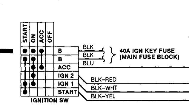
Recently bought a 93 Mazda MPV 3.0L 2WD in which the previous owner had replaced the factory ignition cylinder and switch with a cheapie ignition cylinder from possibly a go-kart or something similar....only 3 of the 5 cylinder wiring terminals were being used...turned key to get vehicle into Accessories/Run...then touched wire hanging from factory ignition switch harness connector to one of the 3 pins wired on the back of the exposed replacement lock cylinder. PROBLEM IS: the bottom blade terminal on the ignition cylinder broke off and I can't figure out how to re-wire this ignition to a dual push-button setup (one button controlling Accessories/Run and the other for Start). I am able to get dash lights, key warning chime, accessories power, and even the starter to crank...but it will not start! I suspect an Ignition Switch to Neutral Safety Switch wiring problem although I am able to shift out of Park with the brake pedal depressed and the Starter will only crank in Park or Neutral, as should be...So the Neutral Safety maybe isn't telling the Fuel Pump to turn on? I'm not sure. I do know that the previous owner had omitted 1 of the 8 wires from the ignition switch harness when they re-wired it...but I am no longer sure which one...DESPITE spending several hours studying the Wiring Diagrams in an attempt to puzzle it out... SO MY QUESTION IS: Can you PLEASE tell me what each of the 8 wires from the Ignition Switch Harness controls? And also, please indicate which ones should have power between themselves when in each Mode: Off, Accessories, Run, and Start? The 8 wire colors I am working with are (I have included voltage data obtained using a multimeter when testing each wire for DC voltage when grounded and no wire connections made @ Ignition Switch Harness): Black/White (to Ignition Coil - 0 volts), Black (to Battery - 12.4 volts, always HOT), Black/Yellow (to Starter - 0 volts), Blue/Red (12.0 volts, always HOT), Black/Red (0 volts), Black (always HOT), Blue (0.20 volts, always HOT...UNLESS connected to Red/Blue wire, then = 0 volts), and Red/Blue (0.66 volts, always HOT...UNLESS connected to Blue wire, then = 0 volts). PLEASE do not just give me images of the wiring diagrams as I have those already and have not found them helpful much. What I really need is one of those Pinout Diagrams that tells what each wire controls and includes a Chart with which pins should have power between them in each mode, used for Switch Testing purposes. Thanks for your help...and patience (as I am self-taught as a mechanic...and still learning...slowly...painfully slowly).
Apr 2, 2014 at 8:20 AM