How does the PCM control the fuel injectors

Tiny
DJ40
  • MEMBER
  • 1996 FORD E-SERIES VAN
  • 5.8L
  • V8
  • 2WD
  • AUTOMATIC
  • 265,000 MILES
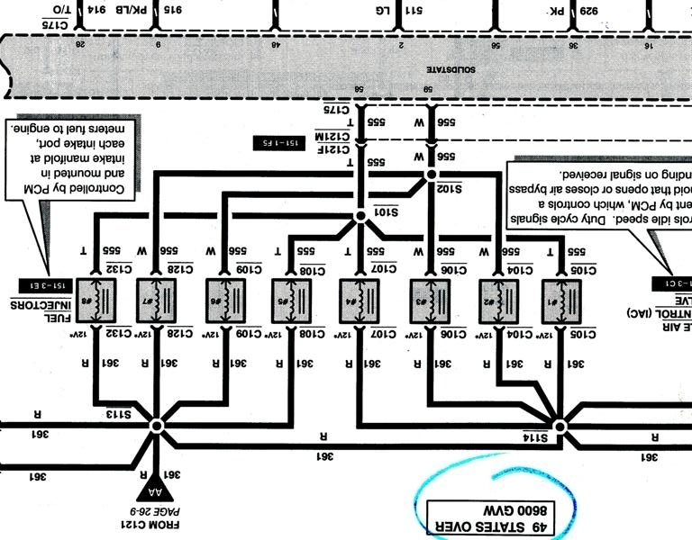
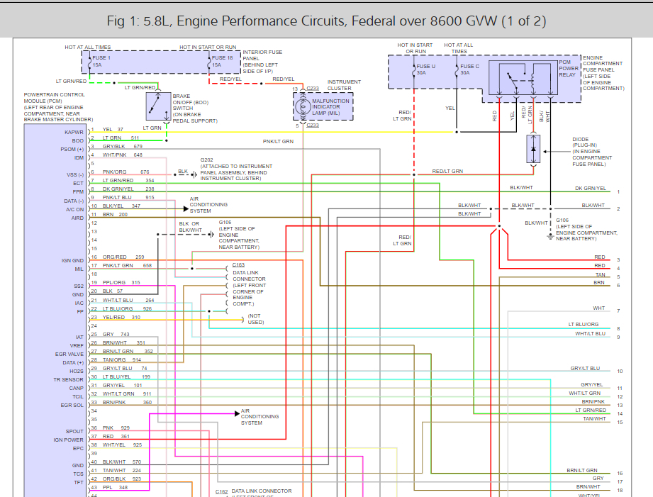
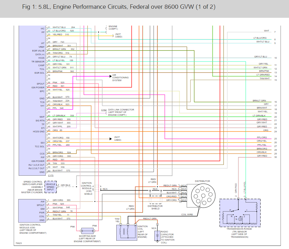
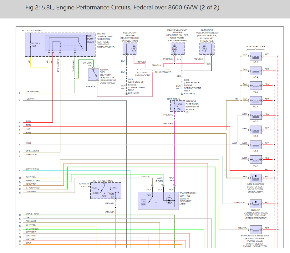
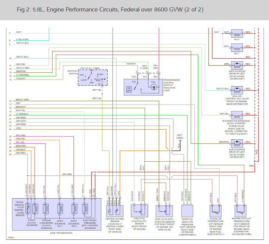
On this van the PCM has only two pins dedicated to sending a signals to the fuel injectors. It appears each pin supplies a signal to four fuel injectors simultaneously. How can that work? I always believed that the cylinders fired in sequence, but how can that be if the PCM is alternately opening four injectors at the same time? I am getting a headache trying to get my brain around how this could possibly operate. Could someone please explain how this works?
Wednesday, September 5th, 2018 AT 6:04 PM

15 Replies

Tiny
ASEMASTER6371
  • MECHANIC
  • 52,797 POSTS
Good evening.

The PCM does not send power to the injectors. Power to them is provided by a fuse controlled circuit from the ignition switch. From there the ground side of the injector goes to the PCM. Based on the cranks sensor signal, the PCM grounds the injector to allow the injector to inject fuel into the cylinder. It makes and breaks the ground many times per second to allow the proper amount of fuel into the cylinder.

Roy
Was this
answer
helpful?
Yes
No
+1
Wednesday, September 5th, 2018 AT 6:17 PM
Tiny
DJ40
  • MEMBER
  • 10 POSTS
That sounds fine, but the wiring diagram in the shop manual does not match that at all. You can see the two pins feeding to the two groups of injectors, pin 59 feeds the odd numbers cylinders, and pin 58 feeds the even numbered cylinders, then on the other side of the injectors you can see all the grounds are tied together. Makes no sense to me at all.
What got me here was I wanted to run a test by turning off each injector to see if the RPM's drop off on each cylinder. They are so hard to get to I was going to add 8 N.C. Momentary push buttons to my breakout box so I could momentarily interrupt the signal to each injector without physically removing each connector. I was shocked to discover I only had two injector pin outs to work with instead of eight. So that ruined my bright idea.
Was this
answer
helpful?
Yes
No
-2
Wednesday, September 5th, 2018 AT 6:42 PM
Tiny
DJ40
  • MEMBER
  • 10 POSTS
I should add, that even thought this is technically a 1996 van it was early on the assembly line and never got the OBDII upgrade. I has the EEC-IV EFI ignition system from 1995 and earlier.
Was this
answer
helpful?
Yes
No
Wednesday, September 5th, 2018 AT 7:02 PM
Tiny
ASEMASTER6371
  • MECHANIC
  • 52,797 POSTS
The system and controls are the same for 1995 and 1996. They are exact wiring diagrams.

That is the way the engineers developed the system. The red wire is common to all eight injectors if you look at the diagram. There are two connectors to each group of four but they are fed by a common feed.

Roy
Was this
answer
helpful?
Yes
No
+2
Thursday, September 6th, 2018 AT 3:36 AM
Tiny
DJ40
  • MEMBER
  • 10 POSTS
If the injectors are connected/wired together in groups of four how is each injector opened individually at its proper time if all four are wired together?
Was this
answer
helpful?
Yes
No
+1
Thursday, September 6th, 2018 AT 4:03 AM
Tiny
ASEMASTER6371
  • MECHANIC
  • 52,797 POSTS
They do not. In that diagram the companion cylinders both get fuel when the PCM grounds the the control. Strange way of controlling it but that is the way Ford designed it.

Roy
Was this
answer
helpful?
Yes
No
Thursday, September 6th, 2018 AT 4:06 AM
Tiny
DJ40
  • MEMBER
  • 10 POSTS
That makes sense but not in relation to the ignition system. This van still has a conventional distributor with a rotor that is sending sequential individual spark to each cylinder. So if the cylinders are getting fuel in simultaneous companion groups of four it would mean fuel is being injected at times when some cylinders are not receiving a spark and the piston is in the wrong position. How can it work if the spark is sequential to the eight spark plugs but the fuel is sent to four companion cylinders? Just does not add up for me.
Was this
answer
helpful?
Yes
No
+1
Thursday, September 6th, 2018 AT 4:38 AM
Tiny
ASEMASTER6371
  • MECHANIC
  • 52,797 POSTS
The piston is at top dead center just that it is on valve overlap not compression.

Roy
Was this
answer
helpful?
Yes
No
+1
Thursday, September 6th, 2018 AT 2:24 PM
Tiny
KEN L
  • MASTER CERTIFIED MECHANIC
  • 42,932 POSTS
The fuel charge enters the engine one half of the rail at a time. The cylinders take in the charge individually. They are not as efficient as they are now. Here are the engine wiring diagrams so people can see how the system works.

Use 2CarPros anytime, we are here to help. Please tell a friend.

Cheers, Ken
Was this
answer
helpful?
Yes
No
+1
Thursday, September 6th, 2018 AT 3:12 PM
Tiny
DJ40
  • MEMBER
  • 10 POSTS
That is the same wiring diagram I have. It still does not explain how it works. You can see that all the injector grounds are tied together and all eight cylinders are controlled by only two wires from the PCM. If four injectors are controlled by the same two wires how can each one inject fuel at the correct moment? Wouldn't all four inject fuel at the same time? That would be okay if all four cylinders were firing at the same time, but they are not. The distributor is firing them in sequence, and each injector must operate in a matching sequence. So how is this possible?
If half the rail is charged at a time what controls that charge? The only thing I see is the fuel line from the gas tank, a fuel pressure valve controlled by the amount of vacuum in the intake manifold, and the pipe splitting off to the two injector rails. There does not appear to be anything that would allow the rails to have separate charging, and nothing in the wiring diagram to indicate any other fuel controls.
Was this
answer
helpful?
Yes
No
Thursday, September 6th, 2018 AT 4:05 PM
Tiny
ASEMASTER6371
  • MECHANIC
  • 52,797 POSTS
I am afraid you are going to have to take the word of the engineers who designed it. They changed it later on where they are controlled individually.

I am not an engineer and cannot give you an engineering answer. There are times we have to accept their designs and go with it.

Roy
Was this
answer
helpful?
Yes
No
+1
Thursday, September 6th, 2018 AT 5:03 PM
Tiny
DJ40
  • MEMBER
  • 10 POSTS
I guess so, but it will continue to bother me. On all the other size engines that year the PCM had an individual pin/wire for each injector. Do not know why they chose the 5.8 to do something radical. I encountered another odd ball in this van. The MAP outputs frequencies to the PCM instead of voltage. That had me stymied for a while. Is it possible they did the same thing with the injectors, where each of the four in a bank respond to a different frequency? If I ever find out how it actually works I will be sure to let you know.
Thanks
Was this
answer
helpful?
Yes
No
Thursday, September 6th, 2018 AT 5:27 PM
Tiny
ASEMASTER6371
  • MECHANIC
  • 52,797 POSTS
The MAP sensor uses a pulse width modulated signal. It is measured in percentage of duty cycle rather than voltage.

Roy
Was this
answer
helpful?
Yes
No
Thursday, September 6th, 2018 AT 5:44 PM
Tiny
DJ40
  • MEMBER
  • 10 POSTS
I finally figured it out. The key is that fuel does not necessarily need to be injected at a precise time. It can be injected at any time during the power stroke. So what is happening is that, at any given interval, four cylinders are simultaneously in a power stroke and are all injected with fuel at the same time, then the distributor fires those four cylinders in sequence as they each come to the top of their respective compression stroke. Not very efficient in my mind but I can finally see how this system works.
Was this
answer
helpful?
Yes
No
Sunday, September 16th, 2018 AT 3:01 PM
Tiny
ASEMASTER6371
  • MECHANIC
  • 52,797 POSTS
Good, glad you understand better. Engineers got smarter in the later years and control each one individually now.

Roy
Was this
answer
helpful?
Yes
No
Sunday, September 16th, 2018 AT 8:00 PM

Please login or register to post a reply.

Sponsored links