2003 Honda CRV Engine Light returns after fillup

Tiny
JOHNNYBME
  • MEMBER
  • 2003 HONDA CRV
Computer problem
2003 Honda CRV 4 cyl All Wheel Drive Automatic

For a month now, the check engine light would come on (I have noticed it usually appears at around a 1/4 tank to 2/3 tank of gas). To reset it, I would unscrew the gas cap and screw it back on. Usually it would go off and if not, I would unscrew it again and rescrew it. The second time always worked.

So I thought perhaps the gas cap is faulty. I bought a new one. And within 5 minutes of driving the light went off. So I thought I fixed the problem. But now the light has come back again (with the new cap).

Does this give clues on what the real problem is? Is it gas cap/tank related or might it be something entirely unrelated.

I just don't understand why with replacing the cap, it goes out, then at half-tank it comes back on.
Tuesday, November 24th, 2009 AT 7:58 AM

7 Replies

Tiny
KHLOW2008
  • MECHANIC
  • 41,815 POSTS
Hi JohnnyBMe,

Get the codes scanned at Autozone, they provide free scanning services, and let me know the exact trouble code.

It could be an EVAP system fault and that would be affected by opening and closing the gas cap. Some evap lines could be clogged or leaking.
Was this
answer
helpful?
Yes
No
+1
Tuesday, November 24th, 2009 AT 6:01 PM
Tiny
JOHNNYBME
  • MEMBER
  • 11 POSTS
Hi and thanks for your reply.

We don't have AutoZone in Canada (as far as I know or can google).

The places I can go to will charge to read the code.

I actually noticed that I don't even have to re-screw the cap.

It just seems like after I fill the tank and get down to about 2/3 tank, the light appears and then magically, at just under 1/2 tank, it disappears again. Then I refill and cycle starts again. I thought that I was fixing it by rescrewing the cap, but apparently nothing to do with it. Strange.
Was this
answer
helpful?
Yes
No
+1
Wednesday, November 25th, 2009 AT 3:06 PM
Tiny
KHLOW2008
  • MECHANIC
  • 41,815 POSTS
Without the trouble code, it is not possible to understand the cause of the problem and from the description, it definitely an EVAP system failure.

The EVAP system concists of many different components and any of them could be the cause.
Was this
answer
helpful?
Yes
No
+1
Thursday, November 26th, 2009 AT 6:54 AM
Tiny
JOHNNYBME
  • MEMBER
  • 11 POSTS
Okay,

I finally got tired of this on and off Check Engine Light and took it in to get codes read.

They came up 2 codes

P0134 - O2 Sensor II Circuit - No Activity

and

P1456 - Evap System Leak (Fuel Tank area)

The mechanic said he reset the engine light and took it for a 10km spin and it did not come back on. He said he had it hooked up to some analysis equipment to test the O2 Sensor and said that there was normal activity. So he wasn't sure why that code came up. But figured there is something not right with the sensor and recommended that I consider replacing it.

About the Evap system leak he thought maybe the gas cap. But I told him that it was happening with the original cap and then even with an aftermarket cap. He recommended I get it smoke tested to determine leak.

Any other suggestions or comments you might have?

By the way, the light did come back on the next day!
Was this
answer
helpful?
Yes
No
+1
Monday, February 8th, 2010 AT 7:59 AM
Tiny
KHLOW2008
  • MECHANIC
  • 41,815 POSTS
Here are the diagnostics for the trouble codes.

DTC P0134: A/F SENSOR (SENSOR 1) SIGNAL STUCK LEAN
1 . Check the A/F sensor (Sensor 1) in the exhaust pipe.
Is it loose?

YES - Reinstall the A/F sensor (Sensor 1)
NO - Go to step 2.

2 . Reset the ECM/PCM

3 . Start the engine. Hold the engine at 3,000 RPM with no load (in Park or neutral) until the radiator fan comes on, then let it idle for 2 minutes.

Is DTC P0134 indicated?
YES - Replace the A/F sensor (Sensor 1)
NO - Intermittent failure, system is OK at this time. Check for poor connections or loose terminals at the A/F sensor (Sensor 1) and the ECM/PCM.

DTC P1456: EVAP CONTROL SYSTEM LEAKAGE (FUEL TANK SYSTEM)
NOTE:
The fuel system is designed to allow specified maximum vacuum and pressure conditions. Do not deviate from the vacuum and pressure tests as indicated in these procedures. Excessive pressure/vacuum would damage the EVAP components or cause eventual fuel tank or system failure.

Special Tools Required

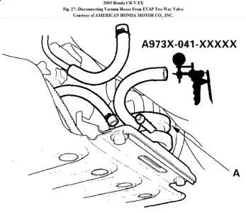
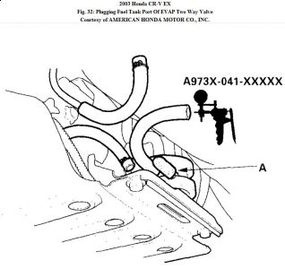
Vacuum pump/gauge, 0-30 in.Hg A973X-041-XXXXX

This is a two-trip code; once cleared, it cannot be reproduced in one trip. Also, certain specific driving and ambient conditions must occur before the ECM/PCM will complete the system checks. Additional test drives may still not meet the specific conditions needed to reproduce the code. If necessary, use the test drive procedures for setting the readiness code (see HOW TO SET READINESS CODES ).

Follow these troubleshooting procedures carefully to ensure the integrity of the system and to confirm the cause of the problem or code.

NOTE:
Fresh fuel has a higher volatility that will create greater pressure/vacuum. The optimum condition for testing is fresh fuel, and must be less than a full tank of fuel. If possible, to assist in leak detection, add 1 gallon of fresh fuel to the tank (as long as it will not fill the tank), just before starting these procedures.

Fuel Fill Cap Check
1 . Check the fuel fill cap (the cap must say "If not tightened 3 clicks check engine light may come on").

Is the correct fuel fill cap installed and properly tightened?

YES - Go to step 2.
NO - Replace or tighten the cap.

2 . Check the fuel fill cap seal and the fuel fill pipe mating surface.

Is the fuel fill cap seal missing or damaged, or is the fuel fill pipe damaged?

YES - Replace the fuel fill cap or the fuel fill pipe.
NO - Go to step 3.

EVAP Bypass Solenoid Valve Test

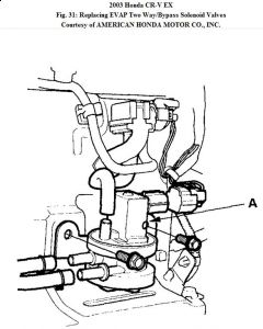
3 . Disconnect both vacuum hoses from the EVAP two way valve (A), and connect a vacuum pump to the canister port on the EVAP two way valve.


https://www.2carpros.com/forum/automotive_pictures/192750_DTC145603CRVFig27_1.jpg


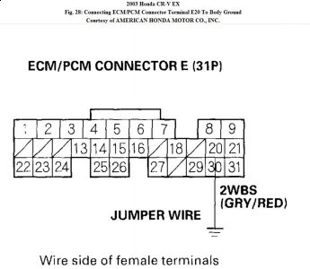
4 . Turn the EVAP bypass solenoid valve ON with the HDS, or connect ECM/PCM connector
terminal E20 to body ground with a jumper wire.


https://www.2carpros.com/forum/automotive_pictures/192750_DTC145603CRVFig28_1.jpg


5 . Turn the ignition switch ON (II).

6 . Apply vacuum to the hose.
Does the valve hold vacuum?

YES - Go to step 7.
NO - Go to step 12.

7 . Turn the ignition switch OFF.

8 . Disconnect the EVAP bypass solenoid valve 2P connector.

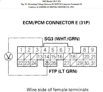
9 . Remove the jumper wire from ECM/PCM connector E (31P), and turn the ignition switch ON (II).

10 . Check for continuity between EVAP bypass solenoid valve 2P connector terminal No. 2 and body ground.


https://www.2carpros.com/forum/automotive_pictures/192750_DTC145603CRVFig29_1.jpg


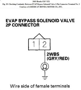
Is there continuity?

YES - Go to step 11.
NO - Repair open in the wire between the EVAP bypass solenoid valve and the ECM/PCM (E20).

11 . Measure voltage between EVAP bypass solenoid valve 2P connector terminal No. 1 and body ground.


https://www.2carpros.com/forum/automotive_pictures/192750_DTC145603CRVFig30_1.jpg


https://www.2carpros.com/forum/automotive_pictures/192750_DTC145603CRVFig31_1.jpg


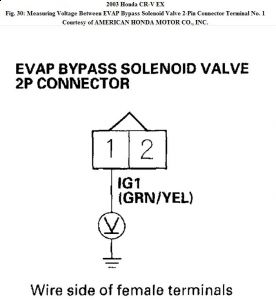
Is there battery voltage?

YES - Replace the EVAP two way/bypass solenoid valves (A).
NO - Repair open in the wire between the EVAP bypass solenoid valve and the No. 4 ACG (10A) fuse.

12 . Plug the fuel tank port (A) of the EVAP two way valve.


https://www.2carpros.com/forum/automotive_pictures/192750_DTC145603CRVFig32_1.jpg


13 . While monitoring FTP sensor voltage with the HDS, or measuring voltage between ECM/PCM connector terminals E4 and E14, slowly pump the vacuum pump once, or until the voltage drops to about 1.5 V.


https://www.2carpros.com/forum/automotive_pictures/192750_DTC145603CRVFig33_1.jpg


Does the voltage drop to 1.5 V and hold for at least 20 seconds?

YES - The EVAP bypass solenoid valve/EVAP two way valve is OK. Go to step 14.
NO - Repair the leakage from the EVAP bypass solenoid valve, EVAP two way valve, or FTP sensor.

Vacuum Hoses and Connections Test

14 . Perform the fuel tank vapor control valve test (see Fuel Tank Vapor Control Valve Test ).

Is the fuel tank vapor control valve OK?

YES - Go to step 15.
NO - Replace the fuel tank vapor control valve.

15 . Tighten the fuel cap 3 clicks.

16 . Start the engine, and let it idle for 5 minutes.

17 . Check the FTP sensor readings.


https://www.2carpros.com/forum/automotive_pictures/192750_DTC145603CRVFig34_1.jpg


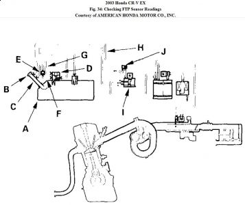
Is the reading above 0.5 kPa of (4 mmHg, 0.16 in.Hg, 2.8 V) pressure?

YES - Update the ECM/PCM if it does not have the latest software, or substitute a known-good ECM/PCM, then recheck (see ECM/PCM UPDATING AND SUBSTITUTION FOR TESTING ). If the symptom/indication goes away with a known-good ECM/PCM, replace the original ECM/PCM.

NO - Check the following parts for leaks:
"Â Fuel tank (A)
"Â Fuel fill cap (B)
"Â Fuel fill pipe (C)
"Â Fuel tank vapor control valve (D)
"Â Fuel tank vapor recirculation valve (E)
"Â Fuel tank vapor recirculation tube (F)
"Â Fuel tank vapor signal tube (G)
"Â Fuel tank vapor control vent tube (H)
"Â Two way valve (I)
"Â FTP sensor (J)
"Â Fuel tank unit base gasket

Repair or replace any leaking parts.

Was this
answer
helpful?
Yes
No
Monday, February 8th, 2010 AT 10:49 AM
Tiny
JOHNNYBME
  • MEMBER
  • 11 POSTS
Thanks for your response.

I guess the smoke test is unfounded? Especially as a first test? Is my mechanic out to lunch on this?

This seems like it might be a costly affair? True?

(Note: I myself don't have the know-how or tools to do this stuff myself).

Edit: I tried giving you feedback points, but system won't allow it because I gave you feedback on another thread (it says to spread it around. But you have been the only one to reply. Which I do appreciate very much)
Was this
answer
helpful?
Yes
No
+1
Monday, February 8th, 2010 AT 10:57 AM
Tiny
KHLOW2008
  • MECHANIC
  • 41,815 POSTS
If your mechanic does not have access to testing procedures, he would not b able to perform them.

The procedures provided are a complete set so you can go through and try the basics, those that you are able to perform without any tools. Some of the steps are not required as it seldom happen that way.

If the appropriate tools are available, it would be much easier and as to the cost, I would put it as a 2 hour job.

You would have to retrieve the trouble codes again to see if they are the same.

Try this to see if it works for retrieving the trouble codes manually with the blinking of the CEL. Use a jumper wire to bridge the DLC terminal # 4 and # 9, turn ignition switch ON and count the blinking of the CEL to get the trouble codes. A prolonged blink = 10 while short flashes = 1 and a short pause is a continuation of the code while a longer flash is an indication of the next code. The codes would repeat once all codes are flashed.

For the DLC, terminal # 1 is the left most where the edges are wider. I can't seem to get any diagrams to show you. If you unseat the DLC from its seat, you would be able to see the wire colors, bridge the Black and Brown wires.

No worries about the feedback points, I still do not understand how it works. Thanks for the intention.

Let me know the trouble codes if you are able to get it.
Was this
answer
helpful?
Yes
No
Monday, February 8th, 2010 AT 11:29 AM

Please login or register to post a reply.

Sponsored links