Pinout diagram needed?

2005 SCION XB
60,506 MILES • 1.5L • 4 CYL • 2WD • MANUAL
Avatar
SCION
  • MEMBER
  • 41 POSTS
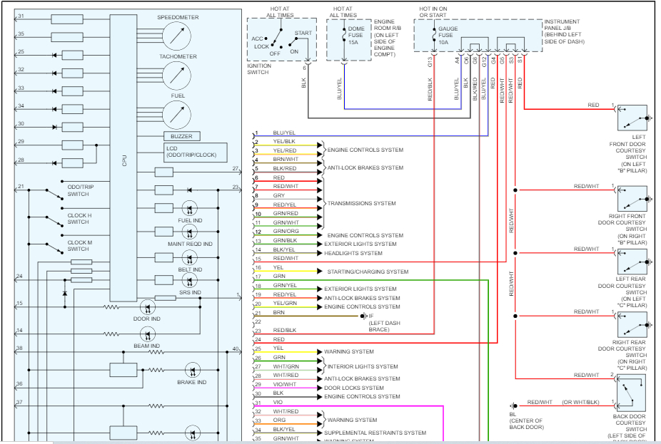
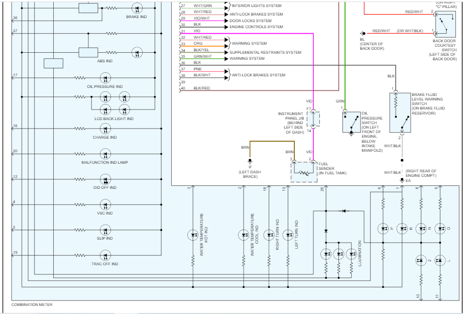
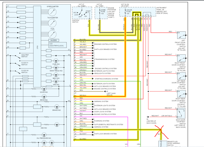
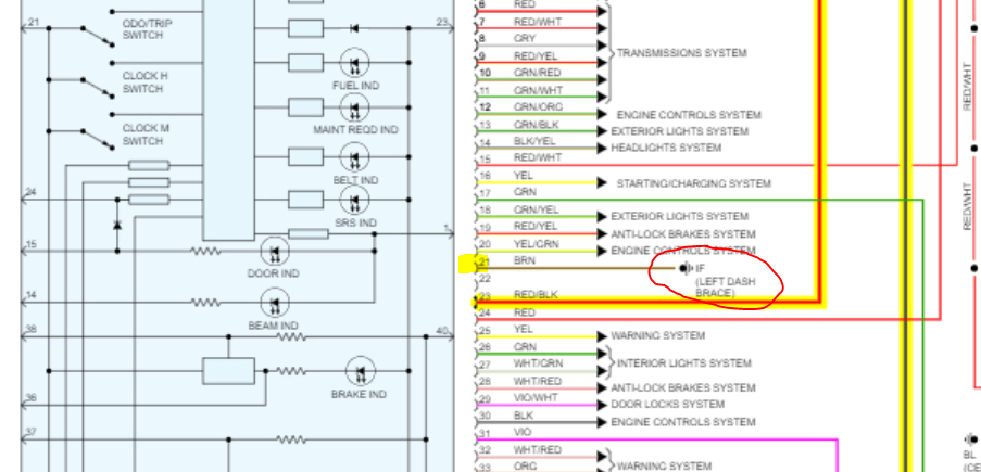
I need a pinout diagram + wire diagram for the vehicle listed above, for the wire diagram. I need it to be something like which color does what, and for the pinout i need it to be like which pin does what. Thanks.
Jun 29, 2023 at 3:57 PM
Advertisement
Avatar
JACOBANDNICKOLAS
  • CAR REPAIR CONTRIBUTOR
  • 110,190 POSTS
Hi,

I would be happy to help, but I need to know what circuit you need it for. Otherwise, there will be pages of pics below and wiring schematics.

For example, do you need the powertrain management schematic and a pinout of the PCM?

If you are not sure, let me know what you are working on and what the vehicle is doing.

Let me know.

Joe
Jun 29, 2023 at 11:15 PM
Avatar
SCION
  • MEMBER
  • 41 POSTS
Hello,

Thank you for your response, but there must be a misunderstanding here, so you see I included all my details (Vehicle, Question) on the title, and I see the title is not showing. So, I'm going to include all my details in this reply, because my question did not include in the title.

------------------------------------------------------------------------------------------------------------------------------------
Vehicle: 2005 Scion xB
Question: How to test a cluster (odometer, speedometer) for a 05 Scion xB.
What I need: Pinout diagram, wire color diagram.

Thank you :)

*P.S - I added a images to show you what a 05 Scion xB cluster looks like
Jun 30, 2023 at 9:40 AM
Avatar
JACOBANDNICKOLAS
  • CAR REPAIR CONTRIBUTOR
  • 110,190 POSTS
Hi,

That makes it easier. LOL I'm not sure why it didn't attach.

Regardless, I attached the wiring schematic for the cluster below. The connector pin identification is included in the schematic.

Note: I had to cut the pic in half to make it readable for you. However, I did overlap the two so you can follow from one to the next.

Let me know if this is what you needed.

Take care,

joe

See pics below.
Jun 30, 2023 at 9:26 PM
Avatar
SCION
  • MEMBER
  • 41 POSTS
Thank you so much for the diagram, Joe, but are you able to tell me which one is the power? Thank you so much.
Jul 1, 2023 at 10:34 AM
Avatar
JACOBANDNICKOLAS
  • CAR REPAIR CONTRIBUTOR
  • 110,190 POSTS
Hi,

You are very welcome. As far as the power supply is concerned, it appears to be the black wire with a red tracer (pin 40). It provides power with the key in the start and run positions. Also, there are a couple of others as well. (Pins 1, 23, and 40)

I attached a pic below and highlighted what I am seeing as the power supplies. Let me know if that helps.

Take care,

Joe

See pic below.
Jul 1, 2023 at 7:23 PM
Avatar
SCION
  • MEMBER
  • 41 POSTS
OMG. Thank you so much, you are so helpful, Joe, you have saved me lots of frustration. I feel dumb, lol. Can you please tell me which one is the negative terminals? Thank you!

Jul 1, 2023 at 8:21 PM
Avatar
JACOBANDNICKOLAS
  • CAR REPAIR CONTRIBUTOR
  • 110,190 POSTS
Hi,

Don't feel dumb. We are all the same. We require being told how. You are no different than anyone else.

Looking at the schematic, it appears pin 21 (brown wire) is ground. See pic below.

Let me know if this helps or if you have questions.

Take care,

Joe

See pic below.
Jul 1, 2023 at 10:20 PM
Avatar
SCION
  • MEMBER
  • 41 POSTS
The kindness is too much, Joe! Thank you so much for helping me! I may come back to this and asked a few more questions in the future, if that's okay. Thank you, Thank you, Thank you!
Jul 2, 2023 at 8:58 AM
Avatar
JACOBANDNICKOLAS
  • CAR REPAIR CONTRIBUTOR
  • 110,190 POSTS
Hi,

You are very welcome. And certainly, you are always welcome to return.

Take care of yourself and I hope you have a great 4th of July.

Joe
Jul 2, 2023 at 1:43 PM
Avatar
SCION
  • MEMBER
  • 41 POSTS
Thank you, Joe. What does the red X mean on pin 36? (Color black)

Happy 4th of July and take care.


Jul 2, 2023 at 1:50 PM
Avatar
JACOBANDNICKOLAS
  • CAR REPAIR CONTRIBUTOR
  • 110,190 POSTS
I put the X there because I didn't want you to think that it was a power or ground supply.

Joe
Jul 2, 2023 at 2:30 PM
Avatar
SCION
  • MEMBER
  • 41 POSTS
Thank you for that, Joe. But I think I am doing something wrong, I am trying to test this cluster, but not the usual way. Here is what I'm using:

Cluster
Cluster wire harness (OEM)
Phone power bank (5V, 8.4, 12V, 16, 20V [you can switch the voltage], 50,000mAH)
USB cable
Jumper cables (small)

Though, on amazon I ordered pinout cables (male to female, I will cut off the female end), they should be here tomorrow to my location, though, I am unsure if I did something wrong. I will be waiting until the cables I ordered are here. In the meantime, can you please tell me what could be wrong? (Wrong voltage, wrong mAH, etc) Thank you, Happy 4th of July.
Jul 2, 2023 at 4:42 PM
Avatar
SCION
  • MEMBER
  • 41 POSTS
Hey Joe! Great news! I got it working! Thank you so much! The cluster has 213K Miles, it's amazing! Thank you, thank you, thank you!
Jul 3, 2023 at 3:21 PM
Avatar
JACOBANDNICKOLAS
  • CAR REPAIR CONTRIBUTOR
  • 110,190 POSTS
Hi,

Thanks for the update. I'm glad to hear you got it working. That's a lot of miles. LOL

Take care and feel free to come back anytime in the future.

Happy 4th!!!

Joe
Jul 3, 2023 at 10:11 PM
Avatar
SCION
  • MEMBER
  • 41 POSTS
Hi Joe! Question, do you know which pins are the speedometer, the gas and RPM gauge pins? Thank you and Happy July!
Jul 4, 2023 at 5:36 PM
Avatar
JACOBANDNICKOLAS
  • CAR REPAIR CONTRIBUTOR
  • 110,190 POSTS
Hi,

I just saw this. I lost power last night at home so sorry for the delay. I looked at the schematic and it isn't indicated. By any chance, have you been able to make progress?

Let me know.

Joe
Jul 6, 2023 at 8:08 PM
Avatar
SCION
  • MEMBER
  • 41 POSTS
Hi, I'm sorry that happened. But, yes, I have made progress, I have found that all the indicators are powered but will turn on if you put it on a negative output. Also, what are these things on the outside of the diagram? It shows the "Speedometer" and other things. Could you help me out with that? Thank you
Jul 7, 2023 at 3:14 PM
Avatar
JACOBANDNICKOLAS
  • CAR REPAIR CONTRIBUTOR
  • 110,190 POSTS
Hi,

Those are the circuits within the cluster. Note that the speedo is hooked into a CPU. That is why I'm struggling to find the pin number for you. What you are seeing is what two manuals provide.

Let me know.

Joe
Jul 7, 2023 at 7:33 PM
Avatar
SCION
  • MEMBER
  • 41 POSTS
Hi Joe, I found out that the Speedometer is not integrated into the motherboard, its actually wired from the mother board (not the primary one) to the gauges. I will send a picture here to show you what I mean. It goes from 1 - 16, is there any information on that? Thank you
Jul 9, 2023 at 10:11 AM
Avatar
JACOBANDNICKOLAS
  • CAR REPAIR CONTRIBUTOR
  • 110,190 POSTS
Hi,

They don't show that. I suspect because it is wired via a CPU. Is that what you are referring to?

Joe
Jul 9, 2023 at 6:53 PM
Avatar
SCION
  • MEMBER
  • 41 POSTS
No, I am saying that the gauges are separated from the motherboard and have 16 pins connecting from the motherboard to the gauges.
Jul 10, 2023 at 8:24 AM
Avatar
JACOBANDNICKOLAS
  • CAR REPAIR CONTRIBUTOR
  • 110,190 POSTS
Hi,

Okay, now I understand. However, that info isn't identified on any of the schematics I have. I'm not sure why. I actually checked two different manuals, and nothing was one either of them. Sorry about that.

Let me know.

Joe
Jul 10, 2023 at 9:48 PM
Avatar
SCION
  • MEMBER
  • 41 POSTS
Aw man, that's a bummer. I wanted to use it for my garage and have the speedometer go up and down and stuff, I guess not. Do you have the cluster wiring diagram for a 2013-2016 Scion FR-S? Thank you.
Jul 11, 2023 at 6:48 AM
Avatar
JACOBANDNICKOLAS
  • CAR REPAIR CONTRIBUTOR
  • 110,190 POSTS
Hi,

I should have access to that information. However, I have to ask a favor. We try to keep the threads specific to one topic and vehicle type. It is more helpful to others.

Would you be able to copy and paste your new request to a new post?

Here is the link to do so:

https://www.2carpros.com/questions/new

I hope you understand.

Take care,

joe
Jul 11, 2023 at 7:38 PM
Repair Safety Notice: This information is for general instructional purposes only. Vehicle repair can be dangerous. Verify all information, follow manufacturer service procedures, use proper tools and safety equipment, and consult a qualified repair shop when needed.