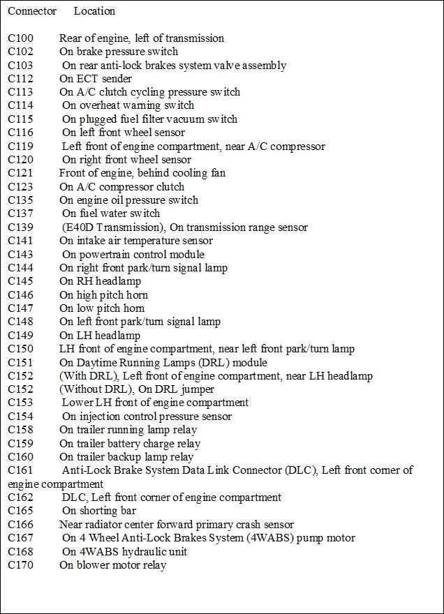
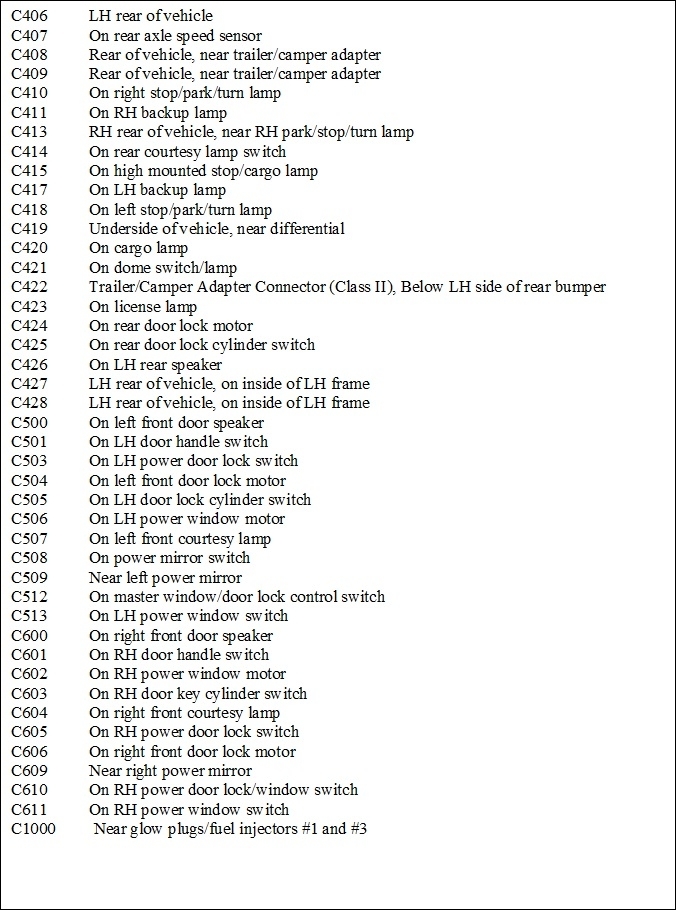
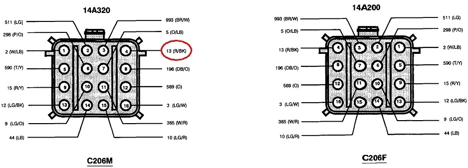
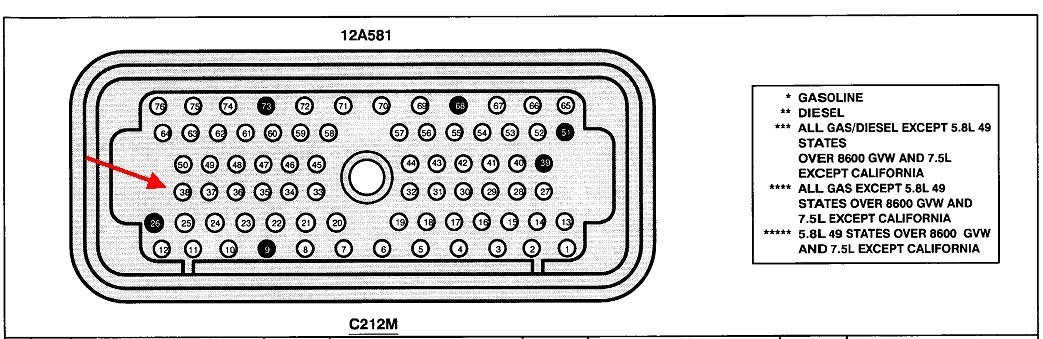
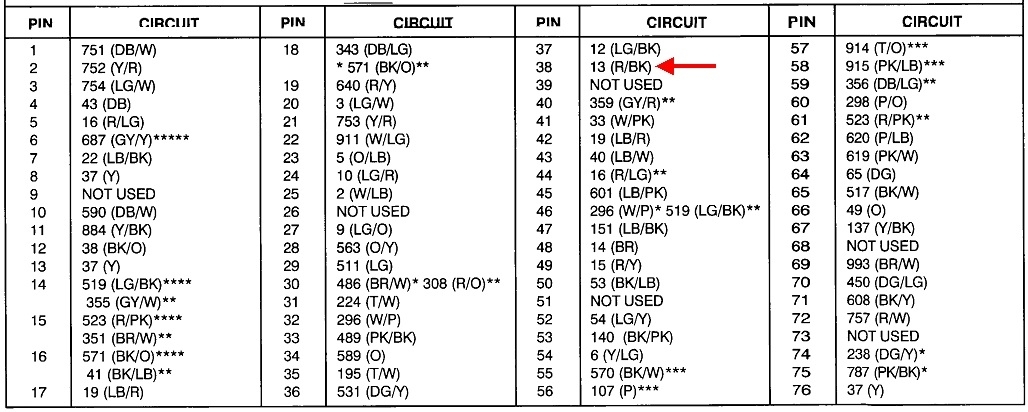
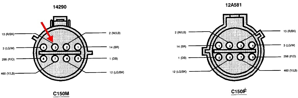
Hey, look what I found. This is a list of connector locations. The last four drawings show the three connectors, in order.
I never approve of cutting or poking a wire to take a reading, but while these connectors provide perfect places to test for voltage, there is a potential pitfall to be aware of. If you start with 50 pounds of pressure at a spigot, you'll have 50 psi at the end of the garden hose when the nozzle is turned off, . . . even if the hose is 99 percent blocked with your foot on it. That 50 psi reading at the nozzle would falsely tell you you can put out a fire with that hose. Open the nozzle and try to get some water to flow, and it can't. To be accurate, you have to measure the pressure at the end of the hose when the nozzle is open. Then what you'd find is 50 psi anywhere in the hose up to your foot, and roughly 0 psi after your foot. In a minute this will make sense in that the spot where the pressure changes significantly tells you where your foot is on the hose.
This is exactly how experienced mechanics become confused with electrical problems. Since you're not allowed to pierce wire insulation, you might think to just unplug the connector, then touch the voltmeter's probe to the terminal. That can work if there is a solid break in the circuit like another disconnected plug or a blown fuse, or a switch turned off, etc, but not if there is a high-resistance break, which is typical of corrosion. The solid break would equate to pinching off the garden hose 100 percent so nothing could get through. The high-resistance break is like the 99 percent restriction from your foot.
Digital voltmeters are similar to a pressure gauge on a compressed air line in a shop. No air actually flows through the gauge for it to do its job. Likewise, almost no current flows through a voltmeter for it to take its readings. Voltage is electrical pressure.
A good example is with a fat battery cable going down to a starter motor. All it takes is one remaining strand of wire out of the hundreds to still be intact, and the voltmeter will show you have 12 volts at the starter, but there's no way you're going to get 200 amps through there. When you try, all that 12 volts will be "dropped" across that high resistance break, leaving you with almost nothing to run the motor, just like standing on the garden hose leaves you with almost nothing to put out the fire.
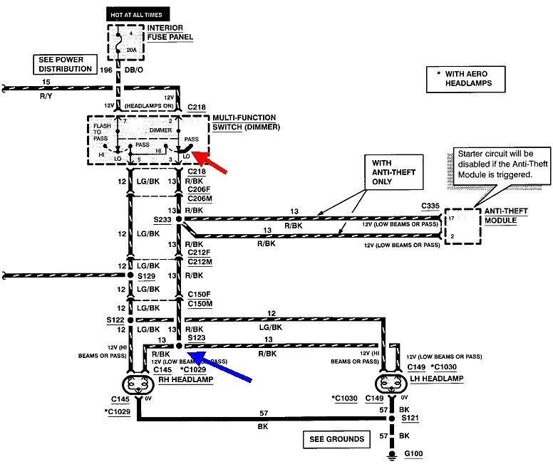
There's two solutions to this voltmeter problem. Both require current to be trying to flow in the circuit, then the results of that high resistance will show up as voltage that is too low, just like water pressure is too low at the end of the hose. The first method is simply to let the head lights try to draw current, (meaning to cause current to want to flow). That means all the connectors have to plugged in, then you can back-probe next to the wire where it goes into its slot at one of those connectors. If you find 12 volts, try again on the other side of the connector, or just move on to the next test point down the circuit. When you find 12 volts, the circuit is good up to that point. You're looking for the first place you find the 12 volts is missing. That's the point of the high resistance, (your foot on the hose).
The alternative is fast and is a better choice when it is too difficult to back-probe a connector. Unplug it, then use a test light instead of a voltmeter. Unlike the voltmeter, a test like requires current to flow through it to make the bulb light up. This has to be the common, cheap test light with an incandescent bulb. There's new electronic test lights on the market that provide inaccurate results the same as voltmeters do. The only way to get enough current flow to light up the bulb is if the circuit has no breaks up to that point. If there's a solid break, the bulb will be off. If there's a high-resistance break, the bulb might glow dimly, but consider that as "off" because only a bright light indicates the circuit is okay to that point.
I almost always use a test light as my first choice of tool. The voltmeter is only required when you have to know the exact voltage at a point in the circuit.
To illustrate how the test light saved the day some years ago, a very experienced new coworker spent a couple of hours on a Chrysler K-Car with a dead radiator fan. There was 12 volts getting to the fan motor's connector, and the ground circuit was good, so he ordered a new fan motor. When it came in, it still didn't run. He showed me how it would run when connected directly to the battery, and he had 12 volts in the plug, but when connected, the motor wouldn't run. To really add to the frustration, the old motor also ran when connected right to the battery. I told him to use a test light, and after his argument against needing that, he figured out the problem in less than a minute.
The old motor had developed tight bearings, and that always causes them to draw much higher current than normal. The circuit was protected by a "fuse link wire", which is still common on a lot of cars and trucks. Fuse link wires are just a slightly smaller diameter than the wires they protect, so they're the weak link in the chain, and their insulation is designed to not burn or melt. They're also a dull color that denotes their current rating, just like fuse colors do. These act like slow-blow fuses. They're used when high start-up current is normal but would instantly blow regular fuses. The old motor caused the fuse link to burn open, so he was right in ordering a new motor. What he wasn't aware of is any time a fuse link wire burns open, the arcing leaves a trail of carbon-tracking behind, identical to what we used to see inside distributor caps. With the motor unplugged, that carbon track was all that was needed for his voltmeter to see 12 volts at the plug, but when connected, almost no current could get through to run either motor. The old motor with tight bearings still ran when connected right to the battery, but he had no way of knowing it was drawing very high current.
The only thing he missed was the need to replace the fuse link wire. You can get them at any auto parts store. Typically they're about 12" long and can be cut to make multiple repairs. Their length in the circuit is irrelevant.
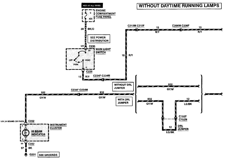
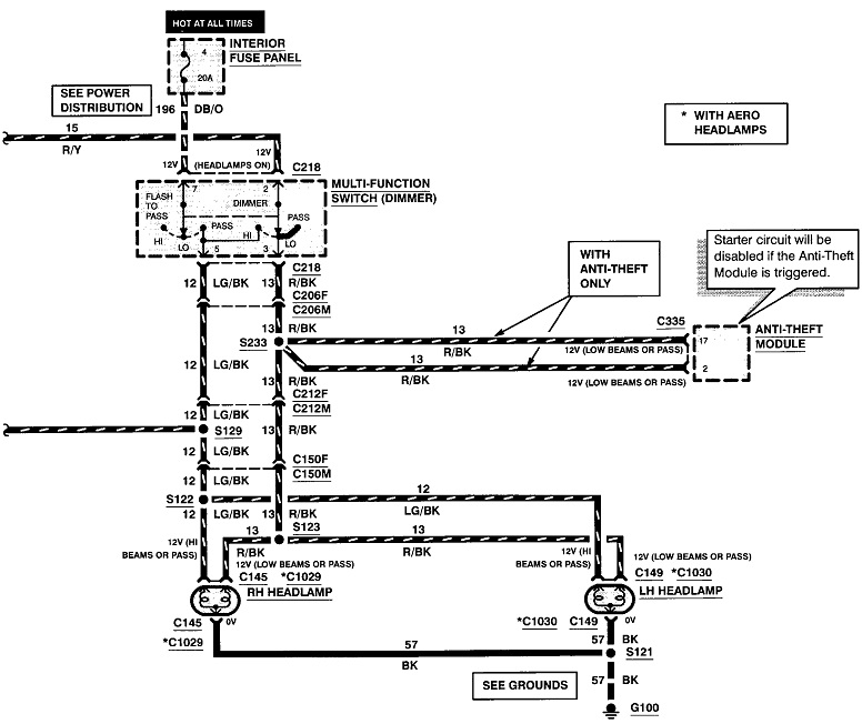
If you're on the verge of becoming confused, this will finish the job, so don't read any further if that's the case. This isn't an important detail, but this is the perfect circuit to explain the most efficient way to do this type of testing. Some people will find the 12 volts missing at the head lights, then work back to connector C150, then back to C212, then to C206, and then to the multi-function switch. If the bad connection is at the switch, it could be an hour of crawling around before they find it. My preference is to start at the switch, then move on to connector C206, then C212, and then to C150, in that direction. I risk wasting time to get all the way to the last splice before I find the cause of the problem.
The most efficient way is to start in the middle, in this case, at connector C212. If the 12 volts is there, the cause is in the last half of the circuit. If the 12 volts is missing, the cause is in the first half starting at the switch. Once you know which half it's in, find a good test point in the middle of that one. Each test eliminates half of the circuit you need to look in for the problem. This assumes all the places to test are easy to get to. Sometimes we have to pick the easiest ones first to save time, then go digging for the hard ones after testing shows that to be necessary.
Images (Click to enlarge)
Jan 10, 2020 at 2:33 PM