Fuse does not test current

Tiny
GDRAGON
  • MEMBER
  • 2000 FORD TAURUS
  • 3.0L
  • V6
  • 2WD
  • AUTOMATIC
  • 145,000 MILES
Fuse 37 and 38 does not have current.
Friday, March 22nd, 2019 AT 11:20 PM

10 Replies

Tiny
ASEMASTER6371
  • MECHANIC
  • 52,797 POSTS
Good morning,

Do you have voltage at the fuses on both sides?

What is the exact reason you have this concern?

Roy
Was this
answer
helpful?
Yes
No
+1
Saturday, March 23rd, 2019 AT 5:10 AM
Tiny
SCGRANTURISMO
  • MECHANIC
  • 4,897 POSTS
Hello,

If the fuse is dead, just replace it with a fuse of the same size and ampere rating. Fuse #37 is a 15A fuse and fuse #38 is a 5A fuse. If you are unfamiliar with how to change a fuse, please go to the link down below.

https://www.2carpros.com/articles/how-to-check-a-car-fuse

Please let us know if there is anything else that we can help you with.

Thanks,
Alex
2CarPros
Was this
answer
helpful?
Yes
No
Saturday, March 23rd, 2019 AT 5:12 AM
Tiny
GDRAGON
  • MEMBER
  • 8 POSTS
I have been having trouble figuring out why my car shuts off when put in drive from out of idle as I step on brake. I was told by street mechanic brake booster. So changed booster and car still stalls as I step on brake. I had some problem with battery drain a week be for this problem. I have checked some ground wires and that took care of the battery drain, but now notice that fuse #37, 38 do not test current. Any help I will be appreciate!
Was this
answer
helpful?
Yes
No
Saturday, March 23rd, 2019 AT 11:47 AM
Tiny
ASEMASTER6371
  • MECHANIC
  • 52,797 POSTS
Got it.

Did you check for voltage at the fuses with a test light or voltmeter?

Roy
Was this
answer
helpful?
Yes
No
Saturday, March 23rd, 2019 AT 12:06 PM
Tiny
GDRAGON
  • MEMBER
  • 8 POSTS
Yes I did, did not get any current with key on.
Was this
answer
helpful?
Yes
No
Saturday, March 23rd, 2019 AT 1:37 PM
Tiny
ASEMASTER6371
  • MECHANIC
  • 52,797 POSTS
I asked about voltage not current. You need a test light or voltmeter to measure voltage.

Roy
Was this
answer
helpful?
Yes
No
Saturday, March 23rd, 2019 AT 1:43 PM
Tiny
GDRAGON
  • MEMBER
  • 8 POSTS
Well yea, no voltage at fuse.I changed fuse but still nothing. What voltage reading should I be looking for just encase as I do wiggle wire test.
Was this
answer
helpful?
Yes
No
Saturday, March 23rd, 2019 AT 10:31 PM
Tiny
ASEMASTER6371
  • MECHANIC
  • 52,797 POSTS
12 volts.

Roy
Was this
answer
helpful?
Yes
No
+1
Sunday, March 24th, 2019 AT 12:07 AM
Tiny
GDRAGON
  • MEMBER
  • 8 POSTS
First of all thank you for the information you have been providing. The Ford manual states that fuse 37, 38 is transmission position switch, GEM park neutral switch. What are they and where are they located?
Was this
answer
helpful?
Yes
No
Sunday, March 24th, 2019 AT 4:59 PM
Tiny
ASEMASTER6371
  • MECHANIC
  • 52,797 POSTS
Did you verify that the fuses are the cause of the draw?

Roy

GEM module

REMOVAL
1. Disconnect the battery ground cable. For additional information, refer to Battery.

CAUTION:
Prior to removal of the module, it is necessary to upload module configuration information to the appropriate scan tool. This information needs to be downloaded into the new module once installed. For additional information, refer to Module Communication Network (Information Bus).
Electronic modules are sensitive to static electrical charges. If exposed to these charges, damage may result.

ImageOpen In New TabZoom/Print

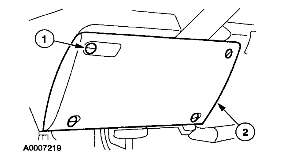
2. Remove the instrument panel steering column cover.
1 Unlock the retainers.
2 Remove the instrument panel steering column cover.

CAUTION: Use care when removing the instrument panel steering column cover or damage to the cover locating tab may occur.

ImageOpen In New TabZoom/Print

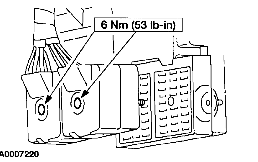
3. Loosen the bolts and disconnect the bulkhead connectors from the instrument panel fuse junction panel.

ImageOpen In New TabZoom/Print

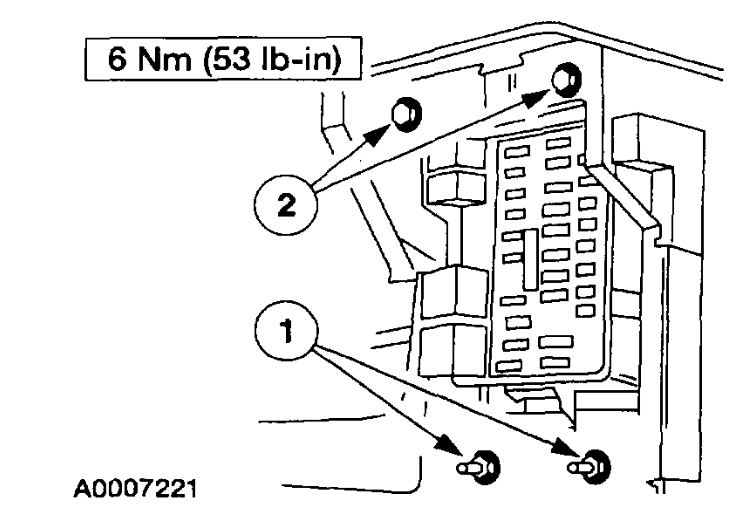
4. Position the instrument panel fuse junction panel aside.
1 Remove the nuts.
2 Remove the bolts.

ImageOpen In New TabZoom/Print

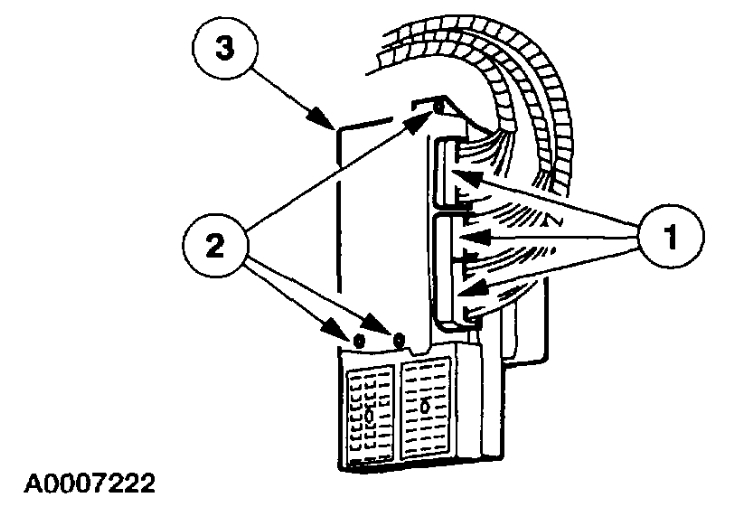
5. Remove the Generic Electronic Module (GEM).
1 Disconnect the electrical connectors.
2 Remove the screws.
3 Remove the GEM.

INSTALLATION
1. To install, reverse the removal procedure.

CAUTION: Once the new module is installed, it is necessary to download the module configuration information from the scan tool equipment into the new module. For additional information, refer to Module Communication Network (Information Bus).

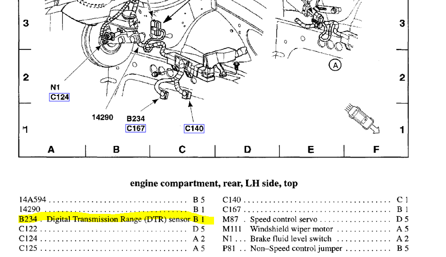
The neutral switch is on top of the transmission under the hood.

Roy
Was this
answer
helpful?
Yes
No
Monday, March 25th, 2019 AT 3:13 AM

Please login or register to post a reply.

Sponsored links