Good evening.
The tank needs to come down to access the pump. Procedures below.
There are two fuel pumps. A low pressure pump in the tank and a high pressure pump on the motor.
Do you know which pump has failed?
Roy
Replacement
Special Tools
EN-48896 - High Pressure Fuel Pump Installation Alignment Gauge
For equivalent regional tools, refer to Special Tools (Diagnostic Tools) See: Engine > Electrical / Mechanical Repair > Special Tools (Diagnostic Tools).
Removal Procedure
1. Relieve the low and high side fuel system pressure. Refer to Fuel Pressure Relief See: Fuel Pressure Release > Procedures > Fuel Pressure Relief.
2. Remove thermostat housing. Refer to Engine Coolant Thermostat Replacement (LEA) See: Thermostat, Engine Cooling > Removal and Replacement > Engine Coolant Thermostat ReplacementEngine Coolant Thermostat Replacement (LFX) See: Thermostat, Engine Cooling > Removal and Replacement > Engine Coolant Thermostat Replacement.
imageOpen In New TabZoom/Print
3. Disconnect the engine wiring harness electrical connector from the high pressure fuel pump.
4. Remove the low pressure feed pipe. Discard the pipe. Refer to Fuel Feed Pipe Replacement See: Fuel Supply Line > Removal and Replacement > Fuel Feed Pipe Replacement.
5. Remove the high pressure pipe. Discard the pipe. Refer to Fuel Feed Intermediate Pipe Replacement See: Fuel Supply Line > Removal and Replacement > Fuel Feed Intermediate Pipe Replacement.
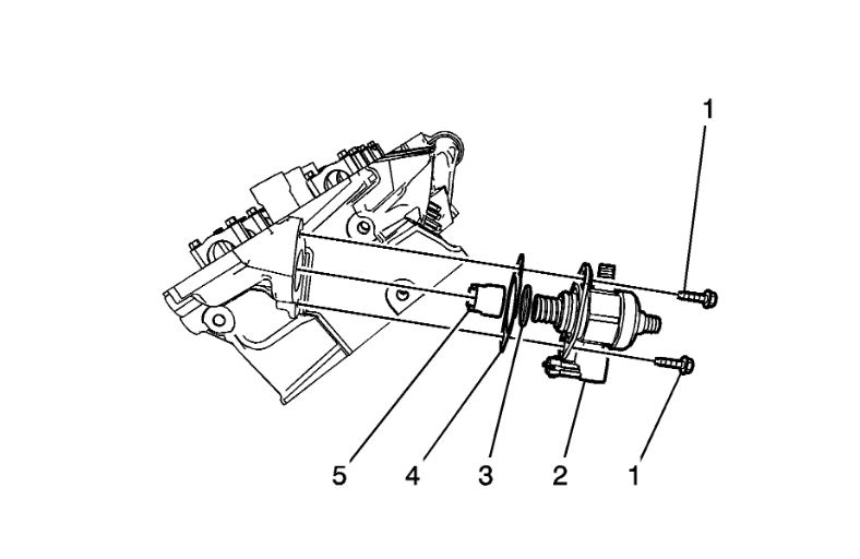
6. Remove and discard the high pressure fuel pump bolts (1).
7. Remove the high pressure fuel pump (2).
8. Remove and discard the high pressure fuel pump O-ring (3).
9. Remove and discard the high pressure fuel pump gasket (4).
10. Remove the high pressure fuel pump roller lifter (5).
Installation Procedure
Note: The camshaft must be in the base circle position before the high pressure fuel pump is installed.
1. Use the EN-48896 - alignment gauge to ensure that the camshaft lobe is in the base circle position. At base circle the tool will be flush with the head.
2. Lubricate the high pressure fuel pump cylinder head bore and roller lifter with camshaft prelube. Refer to Adhesives, Fluids, Lubricants, and Sealers See: Engine > Fluid Types > Adhesives, Fluids, Lubricants, and Sealers.
imageOpen In New TabZoom/Print
Note: The high pressure fuel pump gasket has a retaining feature to hold the pump retaining bolts in place.
3. Install the high pressure fuel pump roller lifter (5).
4. Install a NEW high pressure fuel pump O-ring (3).
5. Position the NEW high pressure fuel pump gasket (4) and bolts (1) to the fuel pump.
6. Install the high pressure fuel pump (2). Force will be required while hand tightening the bolts.
Caution: Refer to Fastener Caution See: Vehicle > Technician Safety Information > Fastener Caution.
7. Tighten the high pressure fuel pump retaining bolts to 15 Nm (11 lb ft).
8. Ensure the high pressure fuel pump and fuel rail fittings are clean prior to assembly.
9. Install a NEW high pressure fuel pipe. Refer to Fuel Feed Intermediate Pipe Replacement See: Fuel Supply Line > Removal and Replacement > Fuel Feed Intermediate Pipe Replacement.
10. Install a NEW fuel feed pipe to the high pressure fuel pump. Refer to Fuel Feed Pipe Replacement See: Fuel Supply Line > Removal and Replacement > Fuel Feed Pipe Replacement.
11. Connect the high pressure fuel pump wiring harness.
12. Install the thermostat housing. Refer to Engine Coolant Thermostat Replacement (LEA) See: Thermostat, Engine Cooling > Removal and Replacement > Engine Coolant Thermostat ReplacementEngine Coolant Thermostat Replacement (LFX) See: Thermostat, Engine Cooling > Removal and Replacement > Engine Coolant Thermostat Replacement.
13. Install the fuel tank cap.
Note: If a fuel leak occurs at the fuel rail, the fuel rail will need to be replaced.
14. Inspect for leaks using the following procedure:
1. Turn ON the ignition, with the engine OFF for 2 seconds.
2. Turn OFF the ignition, for 10 seconds.
3. Turn ON the ignition, with the engine OFF.
4. Inspect for fuel leaks.
15. Install the pressure relief cap to the fuel feed pipe.
Removal Procedure
1. Remove the fuel tank. Refer to Fuel Tank Replacement (AWD) See: Fuel Tank > Removal and Replacement > Fuel Tank Replacement (AWD)Fuel Tank Replacement (FWD) .
Warning: Refer to Gasoline/Gasoline Vapors Warning See: Fuel > Technician Safety Information > Gasoline/Gasoline Vapors Warning.
2. Disconnect the crossover tube from the secondary fuel pump module. Refer to Fuel Tank Fuel Pump Module Replacement - Secondary (Without) See: Fuel Pump > Removal and Replacement > Fuel Tank Fuel Pump Module Replacement - Secondary (With Out).
imageOpen In New TabZoom/Print
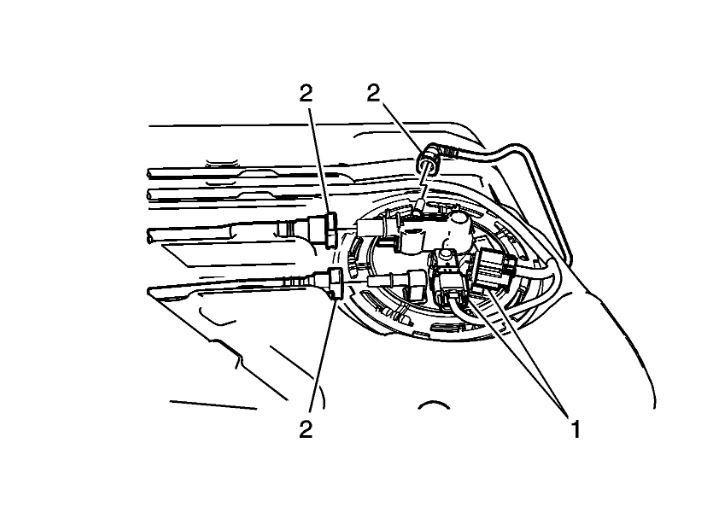
3. Disconnect the electrical connectors (1).
4. Disconnect the fuel and evaporative emission lines (2). Refer to Plastic Collar Quick Connect Fitting Service See: Coolant Line/Hose > Procedures > Plastic Collar Quick Connect Fitting Service.
imageOpen In New TabZoom/Print
5. Using the J-45722 - wrench, remove the cam lock ring (1) by turning counterclockwise.
imageOpen In New TabZoom/Print
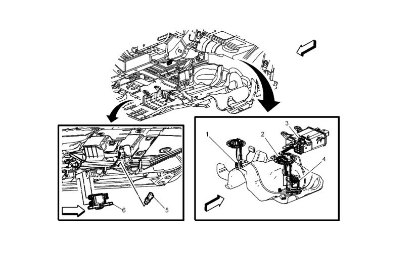
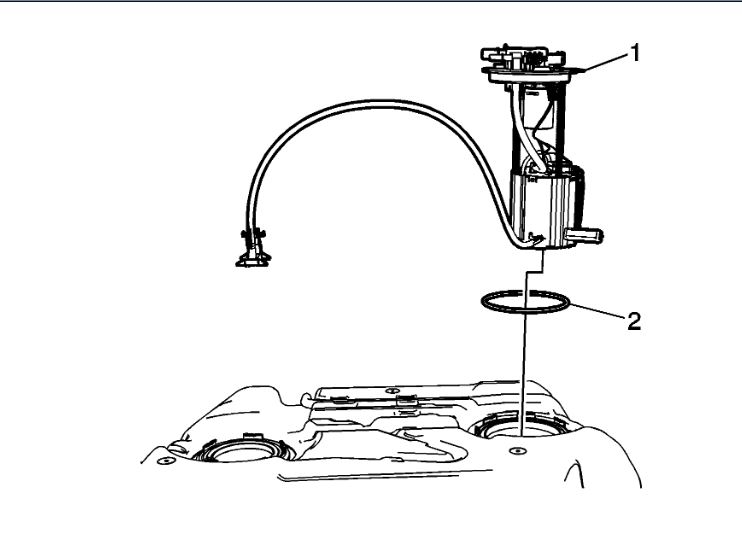
6. Remove the primary fuel tank module (1) and the O-ring (2).
7. If replacing the fuel pump module only, remove the primary fuel level sensor. Refer to Fuel Tank Fuel Pump Module Fuel Level Sensor Replacement See: Fuel Pump > Removal and Replacement > Fuel Tank Fuel Pump Module Fuel Level Sensor Replacement.
Installation Procedure
imageOpen In New TabZoom/Print
1. If replacing the fuel pump module only, install the primary fuel level sensor. Refer to Fuel Tank Fuel Pump Module Fuel Level Sensor Replacement See: Fuel Pump > Removal and Replacement > Fuel Tank Fuel Pump Module Fuel Level Sensor Replacement.
2. Install a NEW O-ring (2) and the primary fuel tank module (1).
imageOpen In New TabZoom/Print
3. Using the J-45722 - wrench, install the cam lock ring (1) by turning clockwise.
imageOpen In New TabZoom/Print
4. Connect the electrical connectors (1).
5. Connect the fuel and evaporative emission lines (2). Refer to Plastic Collar Quick Connect Fitting Service See: Coolant Line/Hose > Procedures > Plastic Collar Quick Connect Fitting Service.
6. Connect the crossover tube to the secondary fuel pump module. Refer to Fuel Tank Fuel Pump Module Replacement - Secondary (Without) See: Fuel Pump > Removal and Replacement > Fuel Tank Fuel Pump Module Replacement - Secondary (With Out).
7. Install the fuel tank. Refer to Fuel Tank Replacement (AWD) See: Fuel Tank > Removal and Replacement > Fuel Tank Replacement (AWD)Fuel Tank Replacement (FWD) .
fuel tank
Warning
Do not allow smoking or the use of open flames in the area where work on the fuel or EVAP system is taking place. Anytime work is being done on the fuel system, disconnect the negative battery cable, except for those tests where battery voltage is required.
1. Ensure that the fuel level in the tank is less than 1/4 full. If necessary, drain the fuel tank to at least this level. Refer to Fuel Tank Draining See: Fuel Tank > Procedures > Fuel Tank Draining.
Warning
Fuel supply lines will remain pressurized for long periods of time after the engine is shutdown. This pressure must be relieved before servicing the fuel system.
2. Relieve the fuel system pressure. Refer to Fuel Pressure Relief See: Fuel Pressure Release > Procedures > Fuel Pressure Relief.
3. Disconnect the negative battery cable. Refer to Battery Negative Cable Disconnection and Connection See: Negative > Removal and Replacement > Battery Negative Cable Disconnection and Connection.
4. Raise and support the vehicle. Refer to Lifting and Jacking the Vehicle See: Vehicle Lifting > Procedures > Lifting and Jacking the Vehicle.
5. Remove the exhaust system. Refer to Exhaust Muffler Replacement See: Muffler > Removal and Replacement > Exhaust Muffler Replacement.
6. Remove the propeller shaft. Refer to Propeller Shaft Replacement See: Drive/Propeller Shaft > Removal and Replacement > Propeller Shaft Replacement.
imageOpen In New TabZoom/Print
Warning
Whenever fuel lines are removed, catch fuel in an approved container. Container opening must be a minimum of 300 mm (12 in) diameter to adequately catch the fluid.
Caution:
Clean all fuel pipe connections and surrounding areas before disconnecting the fuel pipes to avoid contamination of the fuel system.
7. Place a suitable container under the fuel line connection in order to catch any dripping fuel.
8. Remove the evaporative emission canister. Refer to Evaporative Emission Canister Replacement See: Evaporative Emission Control Canister > Removal and Replacement > Evaporative Emission Canister Replacement.
9. Disconnect the chassis fuel supply line (2) from the fuel tank.
imageOpen In New TabZoom/Print
10. Disconnect the fuel filler tube, EVAP vent hose, and fresh air hose from the fuel tank.
11. Disconnect the fuel tank electrical connector and remove the electrical connector retainer from the rear frame.
imageOpen In New TabZoom/Print
Caution:
Do not bend the fuel tank straps. Bending the fuel tank straps may cause damage to the straps.
12. Using a suitable adjustable jack, support the fuel tank.
13. Remove the fuel tank strap nuts and lower the fuel tank straps.
Note:
Be careful to clear the fuel tank strap studs.
14. Lower the front of the fuel tank (with shield), and pull the tank forward to clear the rear drive module.
15. If replacing the fuel tank, remove the fuel tank module assemblies. Refer to Fuel Tank Fuel Pump Module Replacement See: Fuel Pump > Removal and Replacement > Fuel Tank Fuel Pump Module Replacement and Fuel Tank Fuel Pump Module Replacement - Secondary (Without) See: Fuel Pump > Removal and Replacement > Fuel Tank Fuel Pump Module Replacement - Secondary (With Out).
16. If replacing the fuel tank, remove the heat shield, hoses and wiring harness and transfer to the new tank.
Installation Procedure
1. If previously removed, install the fuel tank module assemblies. Refer to Fuel Tank Fuel Pump Module Replacement See: Fuel Pump > Removal and Replacement > Fuel Tank Fuel Pump Module Replacement and Fuel Tank Fuel Pump Module Replacement - Secondary (Without) See: Fuel Pump > Removal and Replacement > Fuel Tank Fuel Pump Module Replacement - Secondary (With Out).
imageOpen In New TabZoom/Print
Note:
Be careful to clear the fuel tank strap studs.
2. Using a suitable adjustable jack, install the fuel tank heat shield and fuel tank assembly to the vehicle.
Caution:
Refer to Fastener Caution See: Vehicle > Technician Safety Information > Fastener Caution.
3. Install the fuel tank straps and the fuel tank strap-to-body nuts and tighten to 20 Nm (15 lb ft).
imageOpen In New TabZoom/Print
4. Connect the fuel tank electrical connector and install the electrical connector retainer to the rear frame.
5. Connect the EVAP vent, and fresh air hoses to the fuel tank.
6. Connect the fuel filler tube to the fuel tank. Tighten the fuel filler tube clamp to 5 Nm (44 lb in).
imageOpen In New TabZoom/Print
7. Connect the chassis fuel supply line (2) to the fuel tank.
8. Install the evaporative emission canister. Refer to Evaporative Emission Canister Replacement See: Evaporative Emission Control Canister > Removal and Replacement > Evaporative Emission Canister Replacement.
9. Install the propeller shaft. Refer to Propeller Shaft Replacement See: Drive/Propeller Shaft > Removal and Replacement > Propeller Shaft Replacement.
10. Install the exhaust system. Refer to Exhaust Muffler Replacement See: Muffler > Removal and Replacement > Exhaust Muffler Replacement.
11. Lower the vehicle.
12. Fill the fuel tank with gasoline.
13. Connect the negative battery cable. Refer to Battery Negative Cable Disconnection and Connection See: Negative > Removal and Replacement > Battery Negative Cable Disconnection and Connection.
14. Prime the fuel system:
1. Cycle the ignition ON for 5 seconds and then OFF for 10 seconds.
2. Repeat the previous step twice.
3. Crank the engine until it starts. The maximum starter motor cranking time is 20 seconds.
4. If the engine does not start, repeat steps 14.1-14.3.
Images (Click to enlarge)
Nov 13, 2018 at 4:05 PM