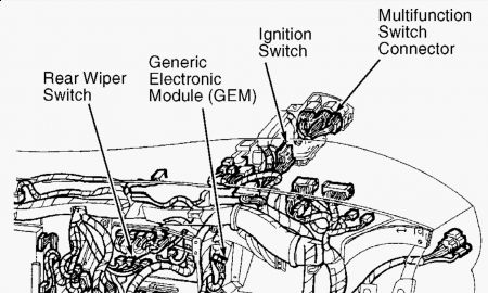
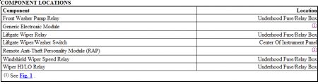
DESCRIPTION & OPERATION All wiper/washer functions are controlled by the multifunction switch and Generic Electronic Module (GEM) located in the instrument panel, between radio and steering column. GEM controls wiper/washer functions through 3 relays. Two relays control wipers and the third relay controls washers. One wiper control relay switches between high (HI) and low (LO) speeds. The other wiper relay switches between run and a dynamic brake (armature short circuit) and is used in interval (INT) mode of operation. Interval delay is controlled by control knob on end of multifunction switch lever. Interval speed is also vehicle speed dependent. Interval delay times decrease as vehicle speed increases.
Testing:
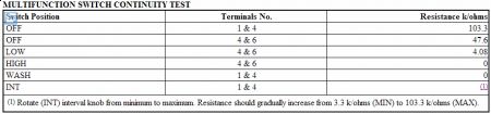
COMPONENT TESTING FRONT WIPER MOTOR Disconnect front wiper motor harness connector. Apply battery ground to terminal No. 3 (Black wire) on motor. Apply battery voltage to terminal No. 2 (White wire) on motor for low speed operation. For high speed operation apply battery voltage to terminal No. 1 (Dark Blue/Orange wire) on motor. Current draw with wiper linkage disconnected should not exceed 3.5 amps at low speed and 5.5 amps at high speed. MULTIFUNCTION SWITCH CONTINUITY TEST Disconnect multifunction switch. Check for continuity between multifunction switch terminals as specified with switch in indicated position. See MULTIFUNCTION SWITCH CONTINUITY TEST table. See Fig. 3 . Replace switch if continuity is not as specified.
If you can scan it with a Ford enabled scane tool, the "B" code will tell you right down to a defective relay, what the problem is.
Saturday, September 12th, 2009 AT 12:33 PM