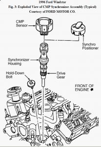
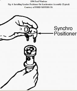
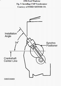
Reply to you email...timing is not adjustable, set the chain and gears right, CMP right and thats it, heres the TS guide for no start conditions.
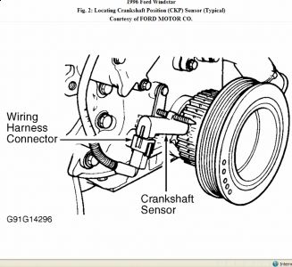
CIRCUIT TEST JD - INTEGRATED IGNITION-NO START Diagnostic Aids When making a voltage check, a ground reading is a value of less than one volt. A power reading is a value of battery voltage, or up to 2 volts less than battery voltage. Perform this test when instructed during QUICK TEST or if directed by other test procedures. This test is used to diagnose the following: ï¬ Crankshaft Position (CKP) sensor. ï¬ CKP wiring harness or connector(s). ï¬ Spark plug wires. ï¬ Faulty Powertrain Control Module (PCM). Fig. 68: CKP Sensor Connector Terminals & Test Circuits Step 1) Check Spark Plugs & Wires Remove and check spark plugs. Check all spark plug wires for damaged insulation or poor connectors. Check primary ignition wiring. Check CKP sensor connector. Repair or replace if necessary. If no faults are found, go to next step. Step 4) Check CKP Circuit To PCM Turn ignition off. Disconnect scan tester from DLC. Disconnect PCM. Check PCM wiring harness connector for damage and repair if necessary. Install Breakout Box (014-000950). Connect PCM wiring harness connector to breakout box. Turn ignition on. Measure voltage between pin No. 21 (CKP+) at breakout box and negative battery terminal. If voltage is not 1-2 volts, go to next step. If voltage is 1-2 volts, go to step 10). Step 5) Check CKP Sensor Turn ignition off. Disconnect CKP wiring harness connector. Turn ignition on. Measure voltage between pin No. 21 (CKP+) at breakout box and negative battery terminal. If voltage is 1-2 volts, go to next step. If voltage is not 1-2 volts, go to step 18). Step 6) Leave ignition on. Measure voltage between pin No. 22 (CKP-) at breakout box and negative battery terminal. If voltage is 1-2 volts, replace CKP sensor and repeat QUICK TEST . If voltage is not 1-2 volts, go to next step. Step 7) If voltage in step 6) was less than 1.0 volt, go to next step. If voltage in step 6) was more than 1.0 volts, go to step 9). Step 8) Turn ignition off. Disconnect PCM from breakout box. Measure resistance between pin No. 22 (CKP-) at breakout box and negative battery terminal. If resistance is more than 10,000 ohms, replace PCM and repeat QUICK TEST . If resistance is 10,000 ohms or less, repair CKP- circuit short to ground. Step 9) Leave PCM disconnected from breakout box. Turn ignition on. Measure voltage between pin No. 22 (CKP-) at breakout box and negative battery terminal. If voltage is less than 0.5 volts, replace PCM and repeat QUICK TEST . If voltage is 0.5 volts or more, repair CKP sensor short to power and repeat QUICK TEST . Step 10) Set DVOM on AC voltage scale. Crank starter while measuring voltage between pin No. NOTE: A break in step numbering sequence occurs at this point. Procedure skips from step 1) to step 4). No test procedures have been omitted. 21 (CKP+) and No. 22 (CKP-) at breakout box. After stabilizing, if AC voltage is less than 0.4 volt, go to next step. If AC voltage is 0.4 volt or more, go to step 60) under CIRCUIT TEST JE. Step 11) Turn ignition off. Disconnect PCM from breakout box. Set DVOM on AC voltage scale. Crank starter while measuring voltage between pin No. 21 (CKP+) and No. 22 (CKP-) at breakout box. After stabilizing, if voltage is less than 0.4 volt, go to next step. If voltage is 0.4 volt or more, replace PCM and repeat QUICK TEST . Step 12) Turn ignition off. Measure resistance between pin No. 21 (CKP+) and No. 22 (CKP-) at breakout box. If resistance is 300-800 ohms, go to step 16). If resistance is not 300-800 ohms, go to next step. Step 13) If resistance in step 12) was more than 300 ohms, go to next step. If resistance in step 12) was 300 ohms or less, go to step 17). Step 14) Check CKP Sensor Turn ignition off. Install EI Diagnostic Harness (007-00059) to Breakout Box (014-000950). Connect EI Diagnostic Harness between CKP sensor and wiring harness connector. Use appropriate overlay. Connect diagnostic harness negative lead to battery negative terminal. Leave positive lead disconnected. Set diagnostic harness box type switch to "4/6" or "8" cylinder position. Measure resistance between breakout box test pins No. 21 (CKP+I) and J31 (CKP+S). If resistance is less than 1050 ohms, go to next step. If resistance is 1050 ohms or more, repair open in CKP+ circuit and repeat QUICK TEST . Step 15) Leave ignition off. Measure resistance between breakout box pin No. 22 (CKP-I) and No. J32 (CKP-S). If resistance is less than 1050 ohms, replace CKP sensor and repeat QUICK TEST . If resistance is 1050 ohms or more, repair open in CKP- circuit. Step 16) Check CKP Sensor & Trigger Wheel Leave ignition off. Check CKP sensor and trigger wheel for damage. Repair or replace as necessary. If CKP sensor and trigger wheel are not damaged, ignition system is okay and testing is complete. If symptom still present, see TESTS W/O CODES - 3.8L article. Step 17) Leave ignition off. Disconnect CKP sensor from wiring harness connector. Measure resistance between breakout box pin No. 21 (CKP+I) and No. J22 (CKP-I). If resistance is more than 1000 ohms, replace CKP sensor and repeat QUICK TEST . If resistance is 1000 ohms or less, repair CKP- circuit short to CKP+ circuit. Step 18) If voltage in step 5) was less than 1.0 volt, go to next step. If voltage in step 5) was 1.0 volt or more, go to step 20). Step 19) Check CKP Sensor For Short To Ground Turn ignition off. Disconnect PCM from PCM breakout box. Measure resistance between breakout box test pins 21 (CKP+I) and negative battery terminal. If resistance is less than 10,000 ohms, repair CKP circuit short to ground and repeat QUICK TEST . If resistance is 10,000 ohms or more, replace PCM and repeat QUICK TEST . Step 20) Check CKP Sensor For Short To Power Turn ignition on. Measure voltage between breakout box test pins 21 (CKP+I) and negative battery terminal. If voltage is more than 0.5 volt, repair CKP+ circuit short to power and repeat QUICK TEST . If resistance is 0.5 volt or less, replace PCM and repeat QUICK TEST . © 2008 Mitchell Repair Information Co., LLC.
Mar 15, 2009 at 7:15 AM