Try testing the ignition switch, acc side may be NG.
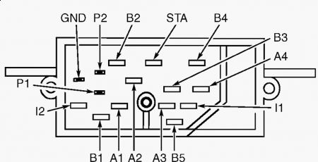
IGNITION SWITCH Test for continuity between specified terminals with switch in each position. See Fig. 2 . If continuity is not as specified, or is poor in any switch position, replace ignition switch. 1. Fig. 2: Identifying Ignition Switch Terminals (Cougar & Thunderbird) Courtesy of FORD MOTOR CO. Continuity should exist between terminals B5 and I1 with switch in START and RUN positions only. Continuity should not exist for all other switch positions. 2. Continuity should exist between terminals B5 and A1 with switch in ACC position only. Continuity should not exist for any other switch position. 3. Continuity should exist between terminals A1 and B1 with switch in RUN position only. Continuity should not exist for any other switch position. 4. Continuity should exist between terminals A2 and B2 with switch in RUN position only. Continuity should not exist for any other switch position. 5. Continuity should exist between terminals A3 and B3 with switch in RUN position only. Continuity should not exist for any other switch position. 6. Continuity should exist between terminals A4 and B4 with switch in RUN position only. Continuity should not exist for any other switch position. 7.
If switch is OK, here's the testing for the A/C.
SATC SYSTEM INOPERATIVE OR OPERATES IMPROPERLY Power Supply To SATC Assembly Partially remove SATC assembly. Turn ignition on. Turn SATC assembly on. Using a test light, probe Purple/Orange wire at 13-pin connector. Probe Brown wire at other connector. If test light does not come on at wires, check for open Purple/Orange wire and repair as necessary. If test light comes on at both wires, go to next step. 1. System Ground Connect ohmmeter lead to good ground. Connect remaining lead to Black wire at 13-pin connector. If resistance is greater than 5 ohms, check for open Black wire. Repair wire as necessary. If resistance is 5 ohms or less, go to next step. 2. SATC Assembly Start engine. Press any A/C or heater button. If A/C or heater actuates, go to next step. If A/C or heater does not actuate, replace SATC assembly. Retest system. 3. Aspirator Installation Check aspirator, hose and elbow installation. If installation or any component is faulty, replace or repair as necessary. If installation is correct, go to next step. 4. Automatic Temperature Control Sensor Output At SATC Assembly Turn ignition on with engine off. Disconnect automatic temperature control sensor. Using voltmeter, check for voltage at White/Orange wire of 13-pin connector. If no voltage exists, check for open White/Orange wire. Repair wire as necessary. If voltage exists, go to next step. 5. Automatic Temperature Control Circuit (White/Orange Wire) Turn ignition off. Using an ohmmeter, check continuity of White/Orange wire between SATC assembly and automatic temperature control connector. If no continuity exists, repair open White/Orange wire between SATC assembly and automatic temperature control connector. If continuity exists, go to next step. 6. Automatic Temperature Control Sensor Return Circuit Using an ohmmeter, check continuity of Pink/Black wire between SATC assembly and aspirator connector. If no continuity exists, repair open Pink/Black wire between SATC assembly and aspirator connector. If continuity exists, replace automatic temperature control sensor. Retest system. 7. Page 1 of 1 A/C-HEATER SYSTEM - AUTOMATIC -1995 Ford Thunderbird LX 5/9/2009
Voltmeter testing:
VOLTMETER TEST Turn ignition on. Observe voltmeter. Turn headlights on. Set heater blower fan to HIGH position. Voltmeter pointer should move toward lower voltage. If pointer does not move, ensure fuses are good. Inspect wiring between battery and instrument cluster. If connections are secure, remove instrument cluster. See INSTRUMENT CLUSTER under REMOVAL & INSTALLATION. Test for battery voltage at instrument cluster. If battery voltage exists, replace gauge. Page 1 of 1 INSTRUMENT PANEL -1995 Ford Thunderbird LX 5/9/2009
May 9, 2009 at 9:07 AM