1996 Ford Taurus Transmission Troubles seems like its stuck

Tiny
ANMLTHNG
  • MEMBER
  • 1996 FORD TAURUS
  • 6 CYL
  • FWD
  • AUTOMATIC
  • 105,000 MILES
I have been trying to figure this out for some time now. It seems like it has reverse and second. I have a OBD2 tester it had a VSS error code of P0500 at first I was told it was the TSS that later I found out not but I replaced the TSS any way. I cleared the code and it hasnt come back.
Now it does have a AX4N trans I have replaced the trans fluid and filter. I tested the voltage at the VSS and it reads.56 volts Haynes manual says it should be 1.5 volts. I even tested it at the PCM and it is the same. I pulled the VSS and did the test in the book it shows it is reading the AC voltage when it is spun. To clarify my thinking it is in Limp Home Mode I can drive it it forward and reverse I jack it up and put it in forward it will not shift I can run it up to 50 MPH and it will not shift into first or overdrive. It stays in 1 gear. Now for another thought I put it in reverse it trys to serge forward than it goes into reverse would that just be a normal act? Also when I have it up on jack stands and going forward it is only in 2ndgear at about 2000 RPMs 50 to 55 MPH I set the cruse and the engine hesitates than floors the gas by the time I can hit the cancel button the engine has raced to 5000 RPMs and the speed goes up also.

Thank You for all your help.
Monday, April 19th, 2010 AT 2:18 PM

4 Replies

Tiny
OBXAUTOMEDIC
  • MECHANIC
  • 3,711 POSTS
Hello,

Need a little more info on the engine size and the submodel.

What Liter engine?

What is the submodel?

There is also a Turbine Speed Sensor and a Speed control module.

The speed control module is located on left front strut to left of master cylinder.

The turbine speed sensors location will vary depending on the engine size in liters and the submodel.

Either of the to components mentioned could be the cause of your problem.

.
Was this
answer
helpful?
Yes
No
Monday, April 19th, 2010 AT 9:35 PM
Tiny
ANMLTHNG
  • MEMBER
  • 1 POST
It is a Taurus GL engine code is U a 3.0 Ltr (182-cid) OHV V6

Are there any illastrations as to where the speed control module is and how to test it? I have replaced the Turbine Speed sensor with a new one before I knew the differerence between the TSS and the VSS. What is the test precedure for testing the TSS and would the voltage on the positive side of the VSS I mentioned before have anything to do with it?

Thank You for your time and help
Was this
answer
helpful?
Yes
No
Monday, April 19th, 2010 AT 11:09 PM
Tiny
OBXAUTOMEDIC
  • MECHANIC
  • 3,711 POSTS
I am at work right now and will get the info and post tonight.

Also did you ever replace the vss? You said you tested it and it appears it tested bad.

I haven't been able to find any diagrams of the speed control module, however it is your criuse control.

.
Was this
answer
helpful?
Yes
No
Wednesday, April 21st, 2010 AT 1:44 PM
Tiny
OBXAUTOMEDIC
  • MECHANIC
  • 3,711 POSTS
CIRCUIT TEST DP - VEHICLE SPEED SENSOR (VSS)
Diagnostic Aids

Perform this test when directed by QUICK TEST. This CIRCUIT TEST is intended to diagnose:

"Â Vehicle Speed Sensor (VSS).
"Â VSS wiring harness circuits. (VSS+ and VSS-).
"Â Powertrain Control Module (PCM).

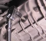
Fig. 35: VSS Circuit & Connector Terminals

Step 1) DTC P0500 This code indicates PCM detected incorrect output from VSS sometime during vehicle operation. Possible causes for this code are:

"Â Faulty VSS.
"Â Open or shorted circuit.
"Â Faulty PCM.

Turn ignition off. Disconnect VSS sensor. Remove PCM 104-pin connector. Inspect connector for damaged pins, corrosion and loose wires. Repair as necessary. Install EEC-V Breakout Box (014-000950), leaving PCM disconnected. Measure resistance between test pin No. 58 and VSS (+) terminal at VSS wiring harness connector. Measure resistance between test pin No. 33 and VSS(-) terminal at VSS wiring harness connector. If resistance readings are less than 5 ohms, go to next step. If either resistance reading is 5 ohms or more, repair open circuit in VSS wiring harness. Clear PCM memory and go to step 27).

Step 2) Check VSS Circuits For Shorts To Power Or Ground Turn ignition off. Ensure PCM and VSS are disconnected. Measure resistance as follows:

"Â Between test pin No. 33 and test pin No. 58 and 71 (VPWR).
"Â Between test pin No. 58 and test pins No. 24, 61, 76 and 103 (PWR GND).
"Â Between test pin No. 58 and test pins No. 71 (VPWR) and 91 (SIG RTN).

If all readings are more than 500 ohms, go to next step. If any reading is 500 ohms or less, repair short in wiring harness. Clear PCM memory and go to step 27).

Step 3) Check VSS Resistance Turn ignition off. Disconnect VSS wiring harness connector. Measure resistance between VSS terminals. If resistance is not 190-250 ohms, replace VSS and go to step 27). If resistance is 190-250 ohms, replace PCM and go to step 27).

NOTE: A break in step numbering sequence occurs at this point. Procedure skips from step 3) to step 5). No test procedures have been omitted.

I will email the whole document to you it will be in an xps format.

.
Was this
answer
helpful?
Yes
No
Wednesday, April 21st, 2010 AT 6:14 PM

Please login or register to post a reply.

Sponsored links