I would suspect a relay
hear r the step taken to determine what is wrong
B: ALL POWER DOOR LOCKS INOPERATIVE
1.Turn ignition switch to OFF position. Check fuse No. 18 (15-amp) in Instrument Panel (I/P) fuse panel. I/P fuse panel is located behind driver's side of instrument panel. If fuse is okay, go to next step. If fuse is blown, replace fuse and check system for normal operation. If fuse fails again, check for short to ground in power feed wire to I/P fuse panel. See WIRING DIAGRAMS .
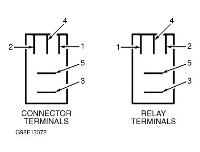
2.Remove all-lock relay located in relay box behind driver's side of instrument panel, to right of steering column. Turn ignition switch to ON position. Use DVOM to measure voltage between ground and all-lock relay connector terminal No. 5 (Black/White wire). See Fig. 1 .
If reading is 10 volts or greater, go to next step. If reading is less than 10 volts, repair open or short to ground in Black/White wire between I/P fuse panel and relay box. Recheck system operation.
3.Remove all unlock relay from relay box. Turn ignition switch to OFF position. Test both the all-lock and all-unlock relays. Go to DOOR LOCK RELAYS under COMPONENT TESTS. If relays are okay, repair open in Black wire between relay box and ground. Ground is located on top of driver's side fender apron. Recheck system operation. If either relay is bad, replace inoperative relay.
Unlock Relay
Locate relay box No. 1 behind instrument panel, right of steering column. Remove door lock relay to be tested. Check continuity using a DVOM. Continuity should exist between relay terminals No. 85 and 86, and also between terminals No. 30 and 87A. See Fig. 2 .
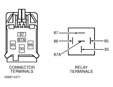
Using fused jumper wires, connect battery voltage to relay terminals No. 85 and 86. Continuity should now exist between relay terminals No. 30 and 87. Replace relay if continuity is not as specified.
Sunday, November 9th, 2008 AT 7:05 AM