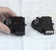
SPEED CONTROL INOPERATIVE (ALL BUT DIESEL)
Unplug harness connector from servo, located near master cylinder. Turn ignition on. Test for battery voltage between servo harness connector pins No. 7 (Tan/Light Blue wire) and No. 1 (Red/Light Blue wire) at servo. If battery voltage does not exist, go to next step. If battery voltage exists, go to step 3).
Turn ignition off. Measure resistance between harness connector pin No. 1 (Red/Light Blue wire) and ground. If resistance is less than one ohm, go to next step. If resistance is not less than one ohm, repair Red/Light Blue wire to ground.
With brake pedal in released position, test for voltage between servo harness connector pins No. 7 (Tan/Light Blue wire) and No. 1 (Red/Light Blue wire). If voltage is zero, stoplight switch is not stuck on. Go to next step. If battery voltage exists, replace stoplight switch.
Turn ignition off. Measure resistance between servo harness connector pins No. 7 (Tan/Light Blue wire) and No. 1 (Red/Light Blue wire). If resistance is less than 20 ohms, go to next step. If resistance is greater than 20 ohms, repair stoplight circuit.
With ignition off and brake pedal released, measure voltage between servo harness connector pins No. 2 (Black/Yellow wire) and No. 1 (Red/Light Blue wire). If battery voltage does not exist, go to next step. If battery voltage exists, go to step 9).
Unplug connector from deactivator switch, located near left frame rail. Measure resistance between switch terminals with brakes released. If resistance is less than one ohm, go to next step. If resistance is not less than one ohm, replace switch, then repeat step 5).
Test for battery voltage at pin No. 1 (Light Green/Yellow wire) at deactivator switch connector. If battery voltage exists, go to next step. If battery voltage does not exist, repair open circuit from fuse panel. See Fig. 2 or Fig. 3.
Measure resistance between deactivator switch connector pin No. 2 (Black/Yellow wire) and pin No. 2 (Black/Yellow wire) at servo harness connector. If resistance is less than one ohm, go to next step. If resistance is greater than 20 ohms, repair Black/Yellow wire.
With no steering wheel switches pressed, measure voltage between servo harness connector pins No. 6 (Light Blue/Black wire) and No. 1 (Red/Light Blue wire). If voltage is zero, ON switch is not stuck. Go to next step. If battery voltage exists, replace ON switch.
With ignition off, measure voltage between servo harness connector pins No. 6 (Light Blue/Black wire) and No. 1 (Red/Light Blue wire) while pressing ON switch. If battery voltage exists, go to step 12). If voltage is less than battery voltage, go to next step.
Press horn while measuring voltage at servo connector pin No. 5 (Dark Green/Orange wire) and ground. If battery voltage exists, replace ON switch. If battery voltage does not exist, repair open feed wire or open switch ground wire. See Fig. 2 or Fig. 3.
With no steering wheel switches pressed, measure resistance between servo harness connector pins No. 6 (Light Blue/Black wire) and No. 5 (Dark Green/Orange wire). If resistance is greater than 3000 ohms, no switches are stuck. Go to next step. If resistance is less than 3000 ohms, replace stuck command switch.
With SET-ACCEL switch pressed, measure resistance between servo harness connector pins No. 6 (Light Blue/Black wire) and No. 5 (Dark Green/Orange wire). If resistance is 640-720 ohms, SET-ACCEL switch is okay. Go to next step. If resistance is not 640-720 ohms, replace SET-ACCEL switch.
Raise and support vehicle with rear wheels clear of ground. Run rear wheels at indicated 30 MPH. Set DVOM to measure AC voltage. Measure voltage between servo harness connector pins No. 8 (Gray/Black wire) and No. 1 (Red/Light Blue wire). If voltage is 4-5 volts, speed signal is okay. Go to next step. If voltage is not 4-5 volts, temporarily substitute known good PSOM, located behind instrument cluster, then retest system.
Disengage cable from servo. Inspect for broken cable by pulling end of cable and observing throttle movement. Replace cable if necessary. If cable is okay, replace servo.
Saturday, February 28th, 2009 AT 8:54 PM


