TEST QB: DIAGNOSTIC TROUBLE CODE P0603, P1605 OR P1633 Diagnostic Aids KAPWR is interrupted when PCM or battery is disconnected. DTC P0603, P1605 or P1633 may be generated during the next PCM power-up. Perform this test when instructed during QUICK TEST or if directed by other test procedures. This test is used to diagnose the following: ï¬ Battery terminal condition. ï¬ Keep Alive Power (KAPWR) circuit routing. ï¬ KAPWR circuit condition. ï¬ Faulty Powertrain Control Module (PCM). 1) DTC P0603, P1605 Or P1633: Check Battery Terminals Inspect battery terminals for corrosion or loose connection. Service as necessary. If battery terminals are okay, go to next step. 2) Check Wiring Harness Inspect wiring harness and connectors for damage or corrosion. Ensure wiring harness is not improperly routed too close to ignition or exhaust components. Service as necessary. If no problems are found, go to next step. 3) Check KAPWR Circuit Turn ignition off. Disconnect PCM 104-pin connector. Inspect connector for loose, damaged or corroded terminals. Repair as necessary. Connect DVOM between PCM connector pin No. 55 (KAPWR) and chassis ground. While observing DVOM, wiggle and bend small sections of wiring harness between PCM and dash panel. If voltage is continuously 10.5 volts or more, go to next step. If at anytime, voltage drops to less than 10.5 volts, isolate open in KAPWR circuit and repair as necessary. 4) Check For Repeat Of DTC P0603, P1605 Or P1633 Perform KOEO ON-DEMAND SELF-TEST . If DTC P0603, P1605 or P1633 is present, replace PCM. If any other DTCs are present, service as necessary. If no DTCs are present, testing is complete. DTC P0603, P1605 or P1633 may have been due to a previous repair. NOTE: After each service or repair procedure has been completed, reconnect all components. Clear DTCs and repeat QUICK TEST procedures to ensure all EEC-V systems are working properly and DTCs are no longer present.
P1395: Perform this test when directed by QUICK TEST. Glow plug relay controls current flow to glow plugs. Glow plug relay "on" time is controlled by Powertrain Control Module (PCM) and is a function of engine oil temperature, barometric pressure and battery voltage. Glow plug "on" time varies between 10-120 seconds. This test is intended to diagnose: ï¬ Glow plug relay. ï¬ Harness circuits (GP/RELAY coil). ï¬ Powertrain Control Module (PCM).
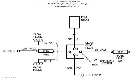
1) DTC P1391, P1393, P1395 & P1396 DTC P1395 or P1396 will set if a cylinder bank has a voltage reading of less than 32-amps or if a cylinder bank has a voltage reading of 8.5 volts less than the other cylinder bank. DTC P1391 or P1393 indicates all 4 glow plugs on one bank are not being powered. Both P1391 and P1393 output together indicates all 8 glow plugs are not being powered. Possible causes for this fault are: ï¬ Faulty glow plug relay. ï¬ Faulty glow plug shunt. ï¬ Open in glow plug circuit(s). ï¬ Faulty glow plug(s). ï¬ Faulty Powertrain Control Module (PCM). Turn ignition on. Using scan tool, select VPWR, EOT, GPCTM, GPMR and GPML PIDs from PID/DATA monitor menu. Verify EOT PID value is less than 86 °F (30 °C) on Econoline or less than 131 °F (55 °C) on Pickup. On all models, verify GPCTM PID value is more than 35 seconds. Compare GPMR and GPML PID values and record both readings. Measure voltage between ground and Black/Orange wire at glow plug relay. See Fig. 29 or Fig. 30 . Relay is located on top right of engine. If battery voltage is present, go to next step. If battery voltage is not present, locate and repair open circuit in Black/Orange wire or replace fusible links. 2) Check For DTC P0380 Perform KOEO ON-DEMAND SELF-TEST . Retrieve DTCs. If DTC P0380 is present, go to next step. If DTC P0380 is not present, go to step 8). 3) DTC P0380 This DTC indicates that PCM has detected a glow plug relay control circuit malfunction. Possible causes for this fault are: ï¬ Short to power. ï¬ Blown fuse. ï¬ Faulty glow plug relay. ï¬ Open or grounded circuit. ï¬ Faulty Powertrain Control Module (PCM). Turn ignition on. Measure voltage between ground and terminal "B" (Red/Light Green wire on Econoline or Red wire on Pickup) at glow plug relay. See Fig. 29 or Fig. 30 . If battery voltage is present, go to next step. If battery voltage is not present, locate and repair open circuit in Red/Light Green wire (Econoline) or Red wire (Pickup). If fuse is blown, check for short to ground. 4) Check Glow Plug Relay Turn ignition off. Disconnect terminal "A" (Purple/Orange wire) at glow plug relay. Measure resistance between terminals "A" and "B" at glow plug relay. If resistance is 1-8 ohms, go to next step. If resistance is not 1-8 ohms, replace glow plug relay. 5) Check For Short To Power Turn ignition off. Disconnect PCM 104-pin connector and inspect for damaged pins, corrosion and loose wires. Repair as necessary. Install Breakout Box (014-00950), leaving PCM disconnected. Turn ignition on. Measure voltage between ground and test pin No. 101 at breakout box. If battery voltage is present, repair short to power. If battery voltage is not present, go to next step. 6) Check For Short To Ground Turn ignition off. Ensure terminal "A" (Purple/Orange wire) at glow plug relay is disconnected. Measure resistance between ground and disconnected Purple/Orange wire. If resistance is more than 10,000 ohms, go to next step. If resistance is 10,000 ohms or less, locate and repair short to ground in Purple/Orange wire. 7) Check For Open Circuit Measure resistance between disconnected Purple/Orange wire and test pin No. 101 at breakout box. If resistance is less than 5 ohms, replace PCM. If resistance is 5 ohms or more, locate and repair open circuit in Purple/Orange wire. 8) Check Glow Plug Relay Turn ignition on. Using scan tool, select EOT and GPCTM PIDs from PID/DATA monitor menu. Verify EOT PID value is less than 86 °F (30 °C) on Econoline or less than 131 °F (55 °C) on Pickup. Measure voltage between ground and terminal "C"at glow plug relay. See Fig. 29 or Fig. 30 . If voltage is present for 30 seconds or more, go to next step. If voltage is not present for 30 seconds or more, replace glow plug relay. NOTE: Glow plug "on" time is dependent on oil temperature and altitude. Glow plugs come on between 1-120 seconds depending on oil temperature and do not come on at all if EOT is more than 86 °F (30 °C) on Econoline or more than 131 °F (55 °C) on Pickup. GPCTM PID value can be used to verify glow plug "on" time. 9) Check Glow Plug Turn ignition off. On cylinder bank that set DTC, disconnect both valve cover gasket connectors. Install Glow Plug Injector Adapter (418-F221) to valve cover gasket. Measure resistance between ground and each of the 4 glow plug circuits on glow plug injector adapter. If any resistance reading is 2 ohms or more, go to next step. On Econoline, if all resistance readings are less than 2 ohms, go to step 12) (for DTCs P1391 and P1395) or step 13) (for DTCs P1393 and DTC P1396). On Pickup, if all resistance readings are less than 2 ohms, go to step 11). 10) Check Valve Cover Gasket Remove valve cover and check glow plug connections. Repair as necessary. If connections are okay, disconnect suspect glow plug connector. Measure resistance between ground and suspect glow plug. If resistance is less than 2 ohms, replace valve cover gasket or Under Valve Cover (UVC) wiring harness. If resistance is 2 ohms or more, replace glow plug. 11) Check Glow Plug Monitoring Circuit (Pickup) Disconnect all 4 valve cover connectors at both left and right cylinder banks. Disconnect PCM 104-pin connector and inspect for damaged pins, corrosion and loose wires. Repair as necessary. Install Breakout Box (014-00950), leaving PCM disconnected. Measure resistance between test pin No. 8 at breakout box and all 8 glow plug circuits at left and right cylinder banks. If all readings are within 2 ohms of each other, replace PCM. If any reading is not within 2 ohms of each other, locate and repair open circuit between valve cover connector and PCM. Verify glow plug shunt nuts are clean and tight. Clear DTCs and repeat QUICK TEST . 14) Check For Open Circuit Measure resistance of White/Violet wire between center terminal of glow plug shunt and test pin No. 8 at breakout box. If resistance is less than 2 ohms, go to next step. If resistance is 2 ohms or more, locate and repair open circuit in White/Violet wire. 15) Compare Right Bank To Left Bank Measure resistance between all 4 glow plug circuits at left cylinder bank and test pins No. 8, 9 and 34 at breakout box. Also, measure resistance between all 4 glow plug circuits at right cylinder bank and test pins No. 8, 9 and 34 at breakout box. If all readings are within 2 ohms of each other, replace PCM. If any reading is not within 2 ohms of each other, repair open in circuit with higher resistance reading. Verify glow plug shunt nuts are clean and tight. NOTE: During KOEO GLOW PLUG MONITOR SELF-TEST it may be necessary to raise engine RPM to maintain system voltage. If unable to maintain system voltage, repair charging system as necessary.
Jun 5, 2010 at 9:26 AM