STARTER MOTOR
Removal & Installation
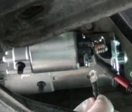
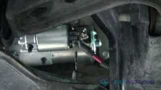
Disconnect negative battery cable. Raise and support vehicle. Remove starter solenoid terminal cover. Disconnect starter solenoid wire connections. On 4.2L engines, remove starter motor mounting nut and ground cable. On all engines, remove starter motor mounting bolts. Remove starter motor. To install, reverse removal procedure. Ensure negative battery cable is installed in proper location. Tighten fasteners to specification. See TORQUE SPECIFICATIONS .
ENGINE DOES NOT CRANK OR RELAY CLICKS
Verify battery condition. If battery is okay, measure voltage between each Red wire at starter relay and ground. Battery voltage should be present at one Red wire only. If battery voltage is present on one Red wire, go to next step. If battery voltage is not present on either Red wire, repair or replace Red wire between battery and starter relay cable. Check system operation.
Measure voltage between starter motor solenoid "B" terminal and ground. See Fig. 3 . If battery voltage is present, go to next step. If battery voltage is not present, clean and tighten battery and solenoid terminal connections. If battery voltage is still not present, replace positive battery cable. Check system operation.
Fig. 3: Identifying Starter Solenoid Terminals (Typical)
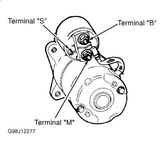
Using jumper wire, connect one end to positive battery terminal and with other end, momentarily touch starter solenoid "S" terminal. See Fig. 3 . If solenoid engages, go to next step. If solenoid does not engage, replace starter motor. See STARTER MOTOR under REMOVAL & INSTALLATION. Check system operation.
Using heavy gauge jumper wire, connect one end to positive battery terminal and with other end, momentarily touch starter solenoid "M" terminal. See Fig. 3 . If starter spins, go to next step. If starter does not spin, replace starter motor. See STARTER MOTOR under REMOVAL & INSTALLATION. Check system operation.
Disconnect starter relay connectors. Disconnect starter motor solenoid connectors. Measure resistance of Red wire between starter relay and starter solenoid. If resistance is less than 5 ohms, replace starter relay. If resistance is 5 ohms or greater, repair or replace Red wire between starter relay and starter solenoid. Check system operation.
ENGINE DOES NOT CRANK & RELAY DOES NOT CLICK
Remove fuse No. 111 (50-amp), located in battery junction box. Check continuity of fuse No. 111. If fuse No. 111 is okay, reinstall fuse and go to next step. If fuse No. 111 is open, install new fuse and go to step 15 .
Remove fuse No. 21 (15-amp), located in central junction box. Check for continuity of fuse No. 21 (15-amp). If fuse No. 21 is okay, reinstall fuse and go to next step. If fuse No. 21 is open, install new fuse, and go to step 18 .
Measure voltage between central junction box fuse No. 21 and ground while holding ignition switch in START position. If battery voltage is present, go to step 6 . If battery voltage is not present, go to next step.
Disconnect ignition switch 15-pin connector. Measure resistance between central junction box fuse No. 21 (15-amp) and ignition switch connector terminal STA (Red/Light Blue wire). See Fig. 4 . If resistance is less than 5 ohms, go to next step. If resistance is 5 ohms or greater, repair poor connection or open in Red/Light Blue wire between ignition switch connector and central junction box. See WIRING DIAGRAMS . Check system operation.
Fig. 4: Identifying Ignition Switch Connector Terminals
Courtesy of FORD MOTOR CO.
Remove battery junction box fuse No. 111 (50-amp). Measure resistance of Light Green/Purple wire between ignition switch harness connector terminal No. B4 and battery junction box fuse No. 111 (50-amp) output cavity. See Fig. 4 . If resistance is less than 5 ohms, replace ignition switch. See appropriate STEERING COLUMN SWITCHES article in ACCESSORIES & EQUIPMENT. If resistance is 5 ohms or greater, repair poor connection or open in Light Green/Purple wire between ignition switch harness connector and output cavity of fuse No. 111 (50-amp). See WIRING DIAGRAMS . Check system operation.
Turn ignition off. Disconnect starter relay connector (Tan/Red wire). Measure voltage between starter relay connector terminal (Tan/Red wire) and ground while momentarily turning ignition switch to START position. If battery voltage is present, replace starter relay. Check system operation. If battery voltage is not present, go to next step (A/T models) or go to step 12 (M/T models).
Disconnect Digital Transmission Range (DTR) sensor 12-pin connector. Measure resistance of Tan/Red wire between DTR sensor connector terminal No. 12 and starter relay connector. See Fig. 5 . If resistance is less than 5 ohms, go to next step. If resistance is 5 ohms or greater, repair Tan/Red wire between DTR sensor connector and starter relay connector. See WIRING DIAGRAMS . Check system operation.
Fig. 5: Identifying Digital Transmission Range Sensor Connector Terminals
Courtesy of FORD MOTOR CO.
Perform DTR sensor adjustment. See DIGITAL TRANSMISSION RANGE (DTR) SENSOR under ADJUSTMENTS. Adjust as necessary. Check system operation. If DTR sensor is adjusted properly, go to next step.
Connect a jumper wire between DTR sensor connector terminals No. 12 (Tan/Red wire) and No. 10 (Dark Blue/Orange wire). See Fig. 5 . Attempt to start vehicle. If vehicle starts, replace DTR sensor. Check system operation. If vehicle does not start, go to next step.
Disconnect Clutch Pedal Position (CPP) jumper 6-pin connector. Measure resistance of Dark Blue/Orange wire between DTR connector terminal No. 10 and CPP jumper connector terminal No. 2. See Fig. 5 and Fig. 6 . If resistance is less than 5 ohms, go to next step. If resistance is 5 ohms or greater, repair Dark Blue/Orange wire between DTR sensor connector and CPP switch. See WIRING DIAGRAMS . Check system operation.
Fig. 6: Identifying Clutch Pedal Position (CPP) Switch Or jumper Connector Terminals
Courtesy of FORD MOTOR CO.
Measure resistance between CPP jumper terminals No. 1 and 2. If resistance is 5 ohms or less, go to step 14 . If resistance is greater than 5 ohms, replace CPP jumper. Check system operation.
Disconnect starter relay connector. Disconnect CPP switch connector. Measure resistance between starter relay connector terminal (Tan/Red wire) and CPP switch connector terminal No. 2 (Dark Blue/Orange wire). See Fig. 6 . If resistance is less than 5 ohms, reconnect starter relay, go to next step. If resistance is 5 ohms or greater, repair open in Tan/Red wire or Dark Blue/Orange wire between CPP and starter relay. See WIRING DIAGRAMS . Check system operation.
Disconnect CPP switch 6-pin connector. Connect a jumper wire between CPP switch connector terminals No. 5 (White/Pink wire) and No. 6 (Gray/Yellow wire). Connect another jumper wire between CPP switch connector terminals No. 1 (White/Pink wire) and No. 2 (Dark Blue/Orange wire). See Fig. 6 . Attempt to start vehicle. If vehicle does not start, go to next step. If vehicle starts, replace CPP switch. Check system operation.
Disconnect central junction box Black 34-pin connector. Measure resistance of White/Pink wire between connector terminal No. 29 and CCP switch connector terminal No. 1. If resistance is less than 5 ohms, replace central junction box. If resistance is 5 ohms or greater, repair open in White/Pink wire between central junction box connector and CPP switch connector. Check system operation.
Momentarily turn ignition switch to START position. Turn ignition off. Remove fuse No. 111 (50-amp) from battery junction box. Check fuse for open. If fuse is okay, system is okay at this time. If fuse is open, go to next step.
Disconnect ignition switch connector. Measure resistance between ignition switch connector terminal B5 (Light Green/Purple wire) and ground. See Fig. 4 . If resistance is greater than 10,000 ohms, go to next step. If resistance is 10,000 ohms or less, repair short to ground in Light Green/Purple wire between ignition switch connector and power distribution box. See WIRING DIAGRAMS .
Remove fuse No. 21 (15-amp) from central junction box. Measure resistance between ignition switch connector terminal STA and ground. See Fig. 4 . If resistance is greater than 10,000 ohms, replace ignition switch. Check system operation. If resistance is 10,000 ohms or less, repair short to ground in Red/Light Blue wire between ignition switch and central junction box. See WIRING DIAGRAMS .
Turn ignition switch to START position momentarily. Turn ignition off. Remove and recheck fuse No. 21 (15-amp). If fuse is not open, no problem is indicated at this time. If fuse is open, install new fuse and go to next step.
Disconnect starter relay connectors. Momentarily turn ignition switch to START position. Turn ignition switch off. Recheck fuse No. 21 (15-amp). If fuse is okay, replace starter relay. Check system operation. If fuse is open, install new fuse and go to next step.
Disconnect CPP switch or CPP jumper connector. Measure resistance between CPP switch or CPP jumper connector terminal No. 1 (White/Pink wire) and ground. See Fig. 6 . If resistance is greater than 10,000 ohms, go to next step (A/T models) or go to step 24 (M/T models). If resistance is less than 10,000 ohms, repair short to ground in White/Pink wire between CPP switch or CPP jumper and central junction box. See WIRING DIAGRAMS . Check system operation.
Place transmission in PARK position. Measure resistance between starter relay connector terminal (Tan/Red wire) and ground. If resistance is greater than 10,000 ohms, replace CPP jumper. Check system operation. If resistance is 10,000 ohms or less, go to next step.
Disconnect DTR sensor connector. Measure resistance between DTR sensor connector terminal No. 10 (Dark Blue/Orange wire) and ground. See Fig. 5 . If resistance is greater than 10,000 ohms, go to next step. If resistance is 10,000 ohms or less, repair short to ground in Dark Blue/Orange wire between DTR sensor and CPP jumper. See WIRING DIAGRAMS . Check system operation.
Measure resistance between DTR sensor connector terminal No. 12 (Tan/Red wire) and ground. If resistance is greater than 10,000 ohms, replace DTR sensor. Check system operation. If resistance is 10,000 ohms or less, repair short to ground in Tan/Red wire between DTR sensor and starter relay. See WIRING DIAGRAMS . Check system operation.
Disconnect starter relay connectors. Measure resistance between CPP switch connector terminal No. 2 (Dark Blue/Orange wire) and ground. If resistance is greater than 10,000 ohms, replace CPP switch. Check system operation. If resistance is 10,000 ohms or less, repair short to ground in Tan/Red wire between CPP switch and starter relay. See WIRING DIAGRAMS . Check system operation.
Thursday, April 15th, 2010 AT 2:22 PM