GLOW PLUG SYSTEM TROUBLE SHOOTING
Connect a 12-volt test lamp between glow plug power relay output and ground. Turn ignition on. Test lamp should light, stay lit for 4-10 seconds, then cycle on and off. If so, go to next step. If test lamp does not light, perform GLOW PLUG TEST C . If test lamp stays on continuously, perform GLOW PLUG TEST B . If test lamp lights for 4-10 seconds and then goes out and stays out, perform GLOW PLUG TEST E .
With test lamp still connected, start engine. Test lamp should cycle on and off for as much as 2 minutes, then turn off. If so, perform GLOW PLUG TEST A . If test lamp continues to cycle on and off after 2 minutes, perform GLOW PLUG TEST D . If test lamp does not light, perform GLOW PLUG TEST E .
NOTE:Perform GLOW PLUG SYSTEM TROUBLE SHOOTING before performing any GLOW PLUG TEST. Performing GLOW PLUG TESTS before trouble shooting glow plug system will result in incorrect test results. After completing indicated GLOW PLUG TEST, return to beginning of GLOW PLUG SYSTEM TROUBLE SHOOTING . DO NOT continue with other GLOW PLUG TESTS. DO NOT replace any parts, unless test results indicate they should be replaced.
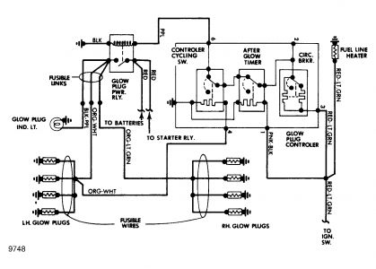
Fig. 2: Glow Plug System Wiring Diagram
"GLOW PLUG" DASH LAMP
Turn ignition off for at least one minute, and then turn ignition on. "GLOW PLUG" dash lamp should light for 4-10 seconds, depending on engine temperature, and then go out. If lamp lights for 4-10 seconds, glow plug lamp system is okay. Perform GLOW PLUG SYSTEM TROUBLE SHOOTING . If lamp does not light and engine is at or near operating temperature, allow engine to cool down and retest. If lamp still does not light, go to next step.
Perform GLOW PLUG TEST C . If test lamp functions as required and "GLOW PLUG" dash lamp did not light in step 1, go to next step. If test lamp does not function properly, fault is within glow plug system. Perform GLOW PLUG SYSTEM trouble shooting.
Remove bulb from "GLOW PLUG" dash lamp and check bulb. If bulb is burned out, replace bulb. Repeat "GLOW PLUG" DASH LAMP trouble shooting. If bulb is good, repair or replace chassis wiring as needed. Repeat "GLOW PLUG" DASH LAMP trouble shooting.
TESTING
INJECTORS TEST
WARNING:When testing injector nozzles, keep spray contained to avoid serious injury. DO NOT allow injector to release line pressure on hands, arms or any part of body, as pressure is high enough to penetrate skin.
Always use CLEAN calibration fluid in Injector Test Stand (Rotunda 014-00300). Install injector on tester. Open test stand valve slightly and operate handle 8-10 times to bleed air from injector. Close valve.
Open tester valve. Slowly lower tester handle and note pressure shown on gauge as injector opens. Repeat several times to obtain accurate reading.
Opening pressure for a NEW injector should be 1800-1950 psi (126-137 kg/cm2 ). If injector opening pressure is below 1425 psi (100 kg/cm2 ) on a used injector, replace injector.
Using test stand, maintain pressure at about 200 psi (14 kg/cm2 ) below opening pressure. No fuel leakage should occur. Slight wetting of tip after 5 seconds is okay. DO NOT wipe tip with fingers. If leakage occurs, injector(s) must be replaced.
GLOW PLUG TEST A - TEST LAMP SIGNAL CORRECT
Remove all leads from glow plugs. Connect a 12-volt test lamp between glow plug power relay output and ground. See Fig. 3 . Turn ignition on. Measure voltage at each glow plug lead whenever test lamp is lit. Voltage should be at least 11 volts. If voltage is okay at all leads, go to step 4. If voltage is not okay at one or more leads, go to next step.
Turn ignition off. Disconnect fusible links from chassis and engine glow plug harnesses. Check continuity of fusible links with an ohmmeter. If fusible links are open, replace fusible(s) link and repeat step 1. If fusible links are okay, go to next step.
With ignition off, disconnect engine harness from chassis connector and all glow plugs. Check resistance between chassis connector left and right bank glow plug terminals, and each glow plug lead. If any resistance is one ohm or more, replace engine harness and check vehicle operation. If resistance is less than one ohm, go to next step.
Turn ignition off. Remove test lamp from power relay. Check resistance between glow plug terminal and metal case of glow plug. If resistance is less than 2 ohms at all glow plugs, glow plug system is okay. Go to ENGINE PERFORMANCE DIAGNOSIS if problem is hard starting. If resistance is more than 2 ohms at any glow plug, replace glow plug(s), reconnect harness and check vehicle operation.
GLOW PLUG TEST B - TEST LAMP ON CONTINUOUSLY
Disconnect all leads from glow plugs. DO NOT reconnect leads to plugs until system has been checked. Connect a 12-volt test lamp to glow plug power relay output and ground. Turn ignition on, but DO NOT start engine. If test lamp cycles but "GLOW PLUG" lamp in dash does not, repair or replace wiring to dash light, or replace bulb, as needed. Repeat GLOW PLUG SYSTEM TROUBLE SHOOTING . If test lamp stays on, go to next step.
With test lamp still connected, turn ignition on. Disconnect wiring harness from control switch. If test lamp goes out, replace control switch and repeat GLOW PLUG SYSTEM TROUBLE SHOOTING . If test lamp stays on, go to next step.
With test lamp still connected, turn ignition on. Disconnect engine harness from chassis harness. If test lamp goes out, replace engine harness and go to step 7. If test lamp stays on, go to next step.
Turn ignition off. Disconnect signal (Purple) lead from power relay. Turn ignition on. If test lamp goes out, repair or replace chassis harness as needed and go to next step. If lamp stays on, go to next step.
Turn ignition off. Remove test lamp and disconnect battery lead from power relay. Reconnect test lamp. With power relay signal lead still disconnected, turn ignition on. If test lamp stays on, repair or replace chassis wiring harness to glow plugs and go to next step. If lamp goes out, replace power relay and go to next step.
With ignition off, remove test lamp from power relay and reconnect all leads, EXCEPT glow plugs. Check continuity from each glow plug lead to power relay output lead. If resistance is less than one ohm for all glow plugs, go to step 8. If resistance is one ohm or greater for one or more glow plugs, go to next step.
With ignition off, disconnect engine harness and fusible links from chassis harness. Check resistance of all fusible links. If resistance of all links is less than one ohm, replace engine harness and go to next step. If resistance of one or more fusible link is one ohm or greater, replace link(s) and repeat step 6.
With ignition off and engine harness disconnected at glow plugs, check resistance between each glow plug terminal and metal shell of glow plug. If resistance is less than 2 ohms for all plugs, glow plug system is okay. Reconnect engine harness to glow plugs and repeat GLOW PLUG SYSTEM TROUBLE SHOOTING .
If resistance for any plug is 2 ohms or greater, replace glow plug(s). Reconnect engine harness to the glow plugs and repeat GLOW PLUG SYSTEM TROUBLE SHOOTING .
GLOW PLUG TEST C - TEST LAMP DOES NOT LIGHT
Ensure ignition has been off for at least one minute, then turn ignition on. If "GLOW PLUG" dash lamp comes on, perform GLOW PLUG TEST E. If not, for engine at normal operating temperature, condition is normal. For coolant temperatures below normal, turn ignition off, wait 2 minutes, and turn ignition back on. If light comes on, perform GLOW PLUG TEST E . If light does not come on, go to next step.
Check batteries for sufficient charge. Batteries should be able to crank engine. If charge is okay, go to next step. If charge is low, charge or replace batteries. Repeat GLOW PLUG SYSTEM TROUBLE SHOOTING .
Turn ignition off. Wait at least one minute, then connect 12-volt test lamp between power relay output and ground. See Fig. 3 . Turn ignition on. If test lamp comes on but "GLOW PLUG" dash lamp does not, repeat GLOW PLUG SYSTEM TROUBLE SHOOTING . If test lamp does not light, go to next step.
Check fusible link between ignition switch and control switch. If fusible link is okay, go to step 8. If fusible link is not okay, replace fusible link, and go to next step.
Repeat GLOW PLUG SYSTEM TROUBLE SHOOTING . If fusible link blows, go to next step. If fusible link does not blow and system operates correctly, testing is complete. If fusible link does not blow and system still does not operate correctly, go to step 8.
Remove signal (Purple) lead from power relay. Replace fusible link. Turn ignition on and then off. If fusible link blows, go to next step. If fusible link does not blow, replace power relay. Repeat GLOW PLUG SYSTEM TROUBLE SHOOTING .
Disconnect chassis harness from engine harness. Replace fusible link. Turn ignition on and then off. If fusible link blows, repair chassis wiring harness and repeat GLOW PLUG SYSTEM TROUBLE SHOOTING . If fusible link does not blow, go to next step.
Turn ignition off for at least one minute. Reconnect all leads, including power relay signal (Purple) lead. Turn ignition back on. Check voltage between power relay signal lead and ground. If voltage is at least 11 volts, go to next step. If less than 11 volts, go to step 10.
With ignition off, check voltage between power relay input terminal and ground. If voltage is at least 11 volts, check power relay ground connection or replace relay. Repeat GLOW PLUG SYSTEM TROUBLE SHOOTING . If voltage is below 11 volts, charge or replace batteries and/or repair wiring from batteries to power relay. Repeat GLOW PLUG SYSTEM TROUBLE SHOOTING .
With ignition off, disconnect power relay signal (Purple) lead. Disconnect engine harness at control switch. Check resistance between control switch connector Pin No. 6 and power relay signal (Purple) lead. See Fig. 3 . If resistance is less than one ohm, go to step 12. If not, go to next step.
With ignition off, disconnect chassis harness from engine harness. Disconnect power relay signal (Purple) lead. Check resistance between chassis side wiring connector terminal No. 6 and power signal lead. See Fig. 3 . If resistance is less than one ohm, replace engine harness. Repeat GLOW PLUG SYSTEM TROUBLE SHOOTING . If not, repair or replace chassis wiring. Repeat GLOW PLUG SYSTEM TROUBLE SHOOTING.
Remove engine harness connector to control switch. Turn ignition on. Check voltage between control switch connector Pin No. 3 and ground. See Fig. 3 . If voltage is at least 11 volts, replace glow plug control switch and repeat GLOW PLUG SYSTEM TROUBLE SHOOTING . If less than 11 volts, go to next step.
Turn ignition off. Disconnect chassis harness from engine harness, Turn ignition back on. Check voltage at Pin No. 3 on chassis side of connector. See Fig. 3 . If voltage is at least 11 volts, replace engine harness. Repeat GLOW PLUG SYSTEM TROUBLE SHOOTING . If not, repair or replace chassis wiring. Repeat GLOW PLUG SYSTEM TROUBLE SHOOTING .
Fig. 3: Glow Plug Test Connections
GLOW PLUG TEST D - TEST LAMP CYCLES CONTINUOUSLY
Disconnect engine harness at control switch. Turn ignition on. Check voltage between control switch connector Pin No. 1 and ground. If voltage is at least 11 volts, turn ignition off and replace control switch. Repeat GLOW PLUG SYSTEM TROUBLE SHOOTING and step 4 of GLOW PLUG TEST A .
If voltage is less than 11 volts, turn ignition off and replace engine harness. Repeat GLOW PLUG SYSTEM TROUBLE SHOOTING and step 4 of GLOW PLUG TEST A .
GLOW PLUG TEST E - TEST LAMP DOES NOT CYCLE
Connect a 12-volt test lamp between glow plug power relay output and ground. Turn ignition on, but DO NOT start engine. If test lamp lights, go to next step. If test lamp does not light, for coolant temperatures of 140 °F (60 °C) or above, condition is normal. For coolant temperatures below 140 °F (60 °C), turn ignition off, wait 5 minutes, and turn ignition back on. If lamp lights, go to next step. If lamp does not light, perform GLOW PLUG TEST C .
Turn ignition off. Disconnect chassis harness from glow plug power relay. Disconnect engine harness from control switch and all glow plugs. Check resistance between control switch connector Pin No. 4 and glow plug relay power output connector. See Fig. 3 . If resistance is less than one ohm, go to step 4. If more than one ohm, go to next step.
Turn ignition off. Disconnect chassis harness from engine harness. Check resistance between chassis harness and glow plug power relay output. If resistance is less than one ohm, replace engine harness. Repeat GLOW PLUG SYSTEM TROUBLE SHOOTING . If more than one ohm, replace fusible link(s) or repair chassis harness. Repeat GLOW PLUG SYSTEM TROUBLE SHOOTING .
With ignition off, check resistance between control switch connector Pin No. 5 and ground. See Fig. 3 . If resistance is less than one ohm, go to next step. If not, repair engine harness ground connection or replace engine harness. Repeat GLOW PLUG SYSTEM TROUBLE SHOOTING .
With ignition off, disconnect engine harness at control switch. Connect all other leads. Check resistance between control switch Pin No. 6 and ground. If resistance is at least 2.5 ohms, replace control switch. Repeat GLOW PLUG SYSTEM TROUBLE SHOOTING as well as step 4 of GLOW PLUG TEST A . If not, replace the power relay. Repeat GLOW PLUG SYSTEM TROUBLE SHOOTING procedures as well as step 4 of GLOW PLUG TEST A .
Dec 13, 2008 at 9:13 PM
