REMOVAL & INSTALLATION
With Key
Disconnect the battery ground.
On tilt columns, remove the upper extension shroud by unsnapping the shroud from the retaining clip at the 9 o'clock position.
Remove the trim shroud halves.
Unplug the wire connector at the key warning switch.
Place the shift lever in PARK and turn the key to ON.
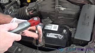
Place a 1/8in. (3mm) wire pin in the hole in the casting surrounding the lock cylinder and depress the retaining pin while pulling out on the cylinder.
When installing the cylinder, turn the lock cylinder to the RUN position and depress the retaining pin, then insert the lock cylinder into its housing in the flange casting. Assure that the cylinder is fully seated and aligned in the interlocking washer before turning the key to the OFF position. This will allow the cylinder retaining pin to extend into the cylinder cast housing hole.
The remainder of installation is the reverse of removal.
Non-Functioning Cylinder or No Key Available
FIXED COLUMNS
Disconnect the battery ground.
Remove the steering wheel.
Remove the turn signal lever.
Remove the column trim shrouds.
Unbolt the steering column and lower it carefully.
Remove the ignition switch and warning buzzer and pin the switch in the LOCK position.
Remove the turn signal switch.
Remove the snapring and T-bolt nuts that retain the flange casting to the column outer tube.
Remove the flange casting, upper shaft bearing, lock cylinder, ignition switch actuator and the actuator rod by pulling the entire assembly over the end of the steering column shaft.
Remove the lock actuator insert, the T-bolts and the automatic transmission indicator insert, or, with manual transmissions, the key release lever.
Upon reassembly, the following parts must be replaced with new parts:
Flange
Lock cylinder assembly
Steering column lock gear
Steering column lock bearing
Steering column upper bearing retainer
Lock actuator assembly
Assembly is a reversal of the disassembly procedure. It is best to install a new upper bearing. Check that the truck starts only in PARK and NEUTRAL.
TILT COLUMNS
Disconnect the battery ground.
Remove the steering column shrouds.
Using masking tape, tape the gap between the steering wheel hub and the cover casting. Cover the entire circumference of the casting. Cover the seat and floor area with a drop-cloth.
Pull out the hazard switch and tape it in a downward position.
The lock cylinder retaining pin is located on the outside of the steering column cover casting adjacent to the hazard flasher button.
Tilt the steering column to the full up position and pre-punch the lock cylinder retaining pin with a sharp punch.
Using a 1/8in. (3mm) drill bit, mounted in a right angle drive drill adapter, drill out the retaining pin, going no deeper than 1/2 in. (13mm).
Tilt the column to the full down position. Place a chisel at the base of the ignition lock cylinder cap and using a hammer break away the cap from the lock cylinder.
Using a 3/8in. (10mm) drill bit, drill down the center of the ignition lock cylinder key slot about 13/4 in. (44mm), until the lock cylinder breaks loose from the steering column cover casting.
Remove the lock cylinder and the drill shavings.
Remove the steering wheel.
Remove the turn signal lever.
Remove the turn signal switch attaching screws.
Remove the key buzzer attaching screw.
Remove the turn signal switch up and over the end of the column, but don't disconnect the wiring.
Remove the 4 attaching screws from the cover casting and lift the casting over the end of the steering shaft, allowing the turn signal switch to pass through the casting. The removal of the casting cover will expose the upper actuator. Remove the upper actuator.
Remove the drive gear, snapring and washer from the cover casting along with the upper actuator.
Clean all components and replace any that appear damaged or worn.
Installation is the reverse of removal.
Thanks for using 2CarPros. Com!
Friday, February 6th, 2009 AT 12:53 PM