Check fuse in the power distribution center, and power relay. Check for power at the coil from + wire.
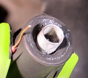
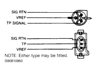
Unplug TPS, turn key on you should get 4-6 volts.
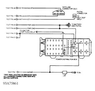
CIRCUIT TEST B - CHECKING VEHICLE BATTERY Diagnostic Aids Enter this CIRCUIT TEST only when directed by CIRCUIT TEST C, CIRCUIT TEST J, CIRCUIT TEST PA, CIRCUIT TEST PB or CIRCUIT TEST PC. This test is only intended to diagnose: � � � Power Control Module (PCM). � � � EEC power relay. � � � Ignition switch. � � � Wiring harness circuits (SIG RTN, PWR GND, VPWR, KAPWR and VREF). To prevent replacement of good components, be aware the following non-EEC related areas and components may be cause of problem: � � � Battery cables and ground straps. � � � Voltage regulator. � � � Alternator. � � � Ignition switch. Fig. 11: Power Relay Circuit ID (B4) TEST PIN NO. 40 & 60 (PWR GND) WIRE COLOR ID 1) Battery Voltage Check Turn ignition on (engine off). Measure battery voltage. If voltage is less than 10.5 volts, recharge or replace battery. If voltage is 10.5 volts or more, go to next step. 2) Check Continuity Of PWR GND Circuit Turn ignition off. Wait 10 seconds. Disconnect PCM. Inspect connector pins and repair if necessary. Install Breakout Box (T83L-50-EEC-IV), leaving PCM connected. Measure resistance between test pins No. 40 and 60 at breakout box and negative battery terminal. If resistance is 5 ohms or more, repair open in PWR GND circuit, and repeat QUICK TEST. If both readings are less than 5 ohms, go to next step. 3) Check For Open Between SIG RTN & PWR GND Circuits At PCM With breakout box installed Application Wire Color 4.0L Black/Light Green CAUTION: Disconnecting vehicle battery will erase stored operating information from Keep-Alive Memory (KAM). If battery is disconnected, vehicle computer and memory systems may lose memory data. Driveability problems may exist until computer systems have completed a relearn cycle. Refer to COMPUTER RELEARN PROCEDURES article in GENERAL INFORMATION section before disconnecting battery. Page 1 of 2 TESTS W/CODES - EEC-IV -1994 Ford Explorer and PCM connected, measure resistance between test pin No. 46 and test pins No. 40 and 60 at breakout box. If readings are 5 ohms or more, replace PCM and repeat QUICK TEST. If resistance readings are less than 5 ohms, go to next step. 4) Check Continuity Of SIG RTN Circuit Ensure ignition is turned off. Measure resistance between test pin No. 46 at breakout box and SIG RTN terminal of Data Link Connector (DLC). If resistance is 5 ohms or more, repair open in SIG RTN circuit and repeat QUICK TEST. If resistance is less than 5 ohms, go to next step. 5) Check KAPWR Circuit Voltage At EEC Power Relay Turn ignition off. Locate relay block in engine compartment. Disconnect EEC power relay from relay block. Turn ignition on. Measure voltage between KAPWR terminal at EEC power relay connector and negative battery terminal. Measure voltage between test pin No. 1 at breakout box and negative battery terminal. If either voltage is 10.5 volts or less, open circuit between KAPWR circuit between EEC power relay and positive battery terminal. If voltage is 10.5 volts or more, go to next step. 6) Check Ignition Circuit Voltage At EEC Power Relay Ensure PCM is connected to breakout box and EEC power relay is disconnected. Turn ignition on. Measure voltage between negative battery terminal and IGNITION terminal at EEC power relay connector. If voltage is less than 10.5 volts, repair open in ignition switch circuit and repeat QUICK TEST. If voltage is 10.5 volts or more, go to next step. 7) Check PWR GND Circuit Continuity Turn ignition off, and wait 10 seconds. With PCM connected to breakout box, measure resistance between negative battery terminal and PWR GND terminal at EEC power relay connector. If resistance is 10 ohms or more, repair open circuit and repeat QUICK TEST. If reading is less than 10 ohms, go to next step. 8) Check VPWR Circuit Continuity Turn ignition off. Measure resistance between test pins No. 37 and 57 (VPWR) at breakout box and VPWR terminal of EEC power relay connector. If resistance is 5 ohms or more, repair VPWR open circuit between EEC power relay and PCM. Repeat QUICK TEST. If reading is less than 5 ohms, go to next step. 9) Check VPWR Circuit Voltage Turn ignition off. Install EEC power relay. Turn ignition on. With PCM connected, measure voltage between test pins No. 37 and 57 (VPWR) and test pins No. 40 and 60 (PWR GND) and 46 (SIG RTN) at breakout box. If voltage is 10.5 volts or more, repair circuit between PCM and EEC power relay. Repeat QUICK TEST . If voltage is less than 10.5 volts, replace EEC power relay. Repeat QUICK TEST. NOTE: Vehicles equipped with Power Distribution Boxes use a diode to provide electrical surge protection for the ignition switch and Ignition Control Module (ICM). If a no-start/no-code condition exists, ensure diode continuity is present in one direction only before going to step 6).
9/14/2008
Sunday, September 14th, 2008 AT 8:24 AM