That engine has 2 sets of flaps inside the intake manifold that are designed to redirect intake air under specific conditions. They had an electric runner control on each one to operate it.
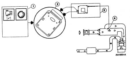
The Intake Manifold Runner Control (IMRC) Electric Actuated system consists of a remote mounted motorized actuator with an attaching cable for each housing on each bank. Some applications will use one cable for both banks. The cable or linkage attaches to the housing butterfly plate levers. The 2.0L (2V) Focus/Escort IMRC uses a motorized actuator mounted directly to a single housing without the use of a cable. Each IMRC housing is an aluminum casting with two intake air passages for each cylinder. One passage is always open and the other is opened and closed with a butterfly valve plate. The housing uses a return spring to hold the butterfly valve plates closed. The motorized actuator houses an internal switch or switches, depending on the application, to provide feedback to the PCM indicating cable and butterfly valve plate position.
Below approximately 3000 rpm , the motorized actuator will not be energized. This will allow the cable to fully extend and the butterfly valve plates to remain closed. Above approximately 3000 rpm , the motorized actuator will be energized. The attaching cable will pull the butterfly valve plates into the open position. Some vehicles will activate the IMRC near 1500 rpm .
WARNING: SUBSTANTIAL OPENING AND CLOSING TORQUE IS APPLIED BY THIS SYSTEM. TO PREVENT INJURY, BE CAREFUL TO KEEP FINGERS AWAY FROM LEVER MECHANISMS WHEN ACTUATED.
1. The PCM uses the TP sensor and Crankshaft Position (CKP) signals to determine activation of the IMRC system. There must be a positive change in voltage from the TP sensor along with the increase in rpm to open the valve plates.
2. The PCM uses the information from the input signals to control the IMRC motorized actuator based upon rpm and changes in throttle position.
3. The PCM energizes the actuator to pull the butterfly plates open with the cable(s) or linkage.
4. The IMRC housing contain butterfly plates to allow increased air flow.
Aug 25, 2010 at 1:59 PM