Hi,
Here are the directions for the accessory drive belt replacement. Let me know if this helps. The attached pics correlate with the directions. The attached pics correlate with the directions.
_____________________________________
2010 Land Rover Range Rover (LM) V8-5.0L SC
Accessory Drive Belt
Vehicle Engine, Cooling and Exhaust Engine Drive Belts, Mounts, Brackets and Accessories Drive Belt Service and Repair Removal and Replacement Accessory Drive Belt
ACCESSORY DRIVE BELT
Accessory Drive Belt
This is a "Trustmark Authoring Standards (TAS) Repair Procedure"
- TAS style procedures can be identified by steps that have no accompanying step text and the magenta color of the electrical connectors and fasteners such as nuts, bolts, clamps or clips.
- TAS removal and installation procedures use a sequence of color illustrations to indicate the order to be followed when removing/disassembling or installing/assembling a component.
- Many of the TAS procedures will have the installation information within the removal steps.
- The TAS color illustrations use a variety of symbols to indicate important details of the procedures. It is important to understand these symbols in order to properly used the TAS procedures.
Refer to How to Use TAS Procedures and TAS Symbol Glossary at Vehicle | Description and Operation for additional information on these TAS procedures.
For additional information, refer to How to Use TAS Procedures See: Vehicle > Components > How to Use TAS Procedures
Removal
NOTE:
Some variation in the illustrations may occur, but the essential information is always correct.
NOTE:
Removal steps in this procedure may contain installation details.
1 Disconnect the battery ground cable.
For additional information, refer to See: Battery > Procedures > Battery and Charging System
WARNING: Make sure to support the vehicle with axle stands.
2 Raise and support the vehicle.
For additional information, refer to Supercharger Belt See: Drive Belt > Removal and Replacement > Supercharger Belt
pic 1
CAUTION: Always protect the cooling pack elements to prevent accidental damage.
NOTE:
The thread is right handed.
NOTE:
Some variation in the illustrations may occur, but the essential information is always correct.
Special Service Tool
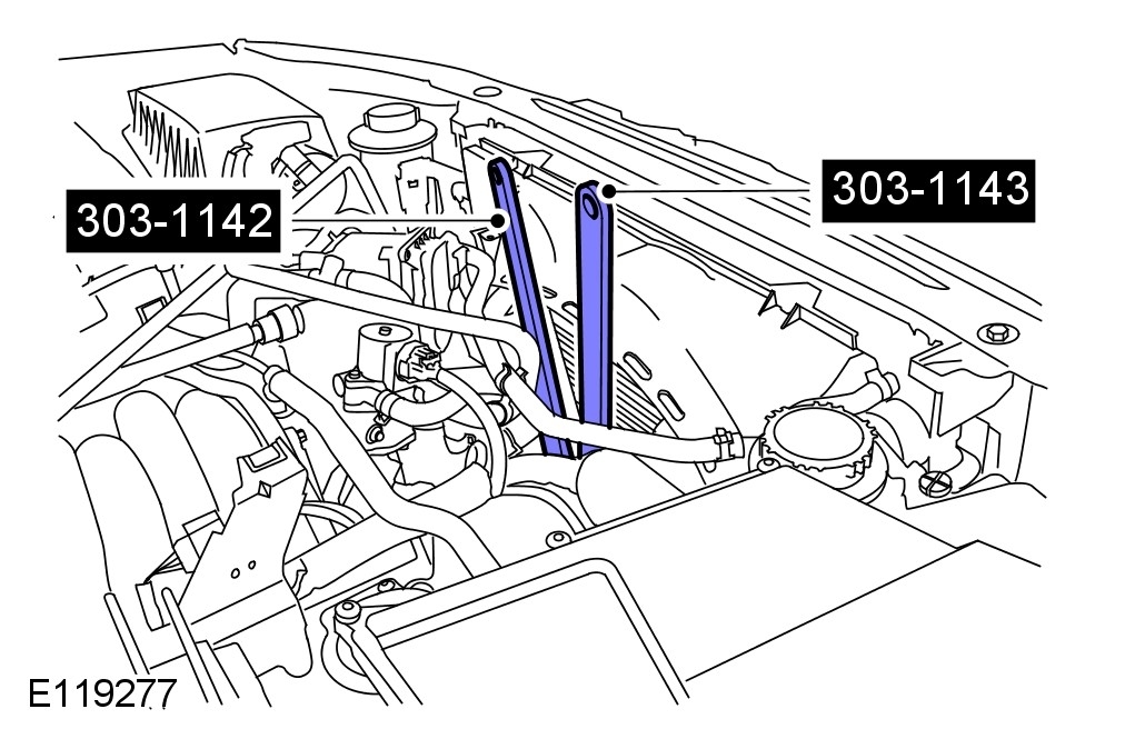
pic 2
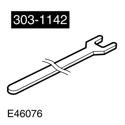
Viscous Coupling Wrench, 303-1142
Special Service Tool
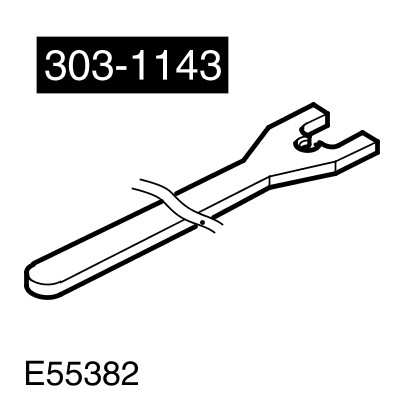
pic 3
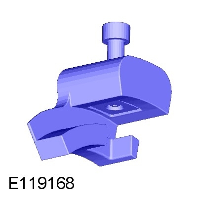
Viscous Coupling Holding Tool, 303-1143
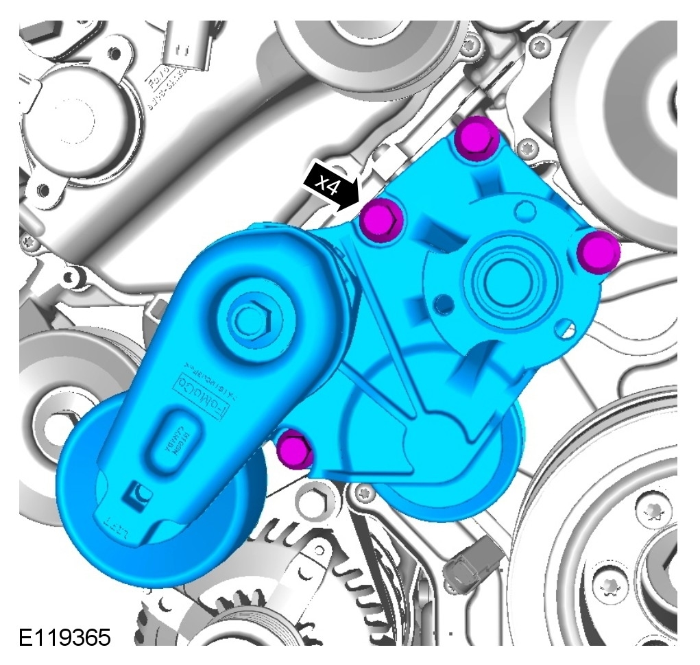
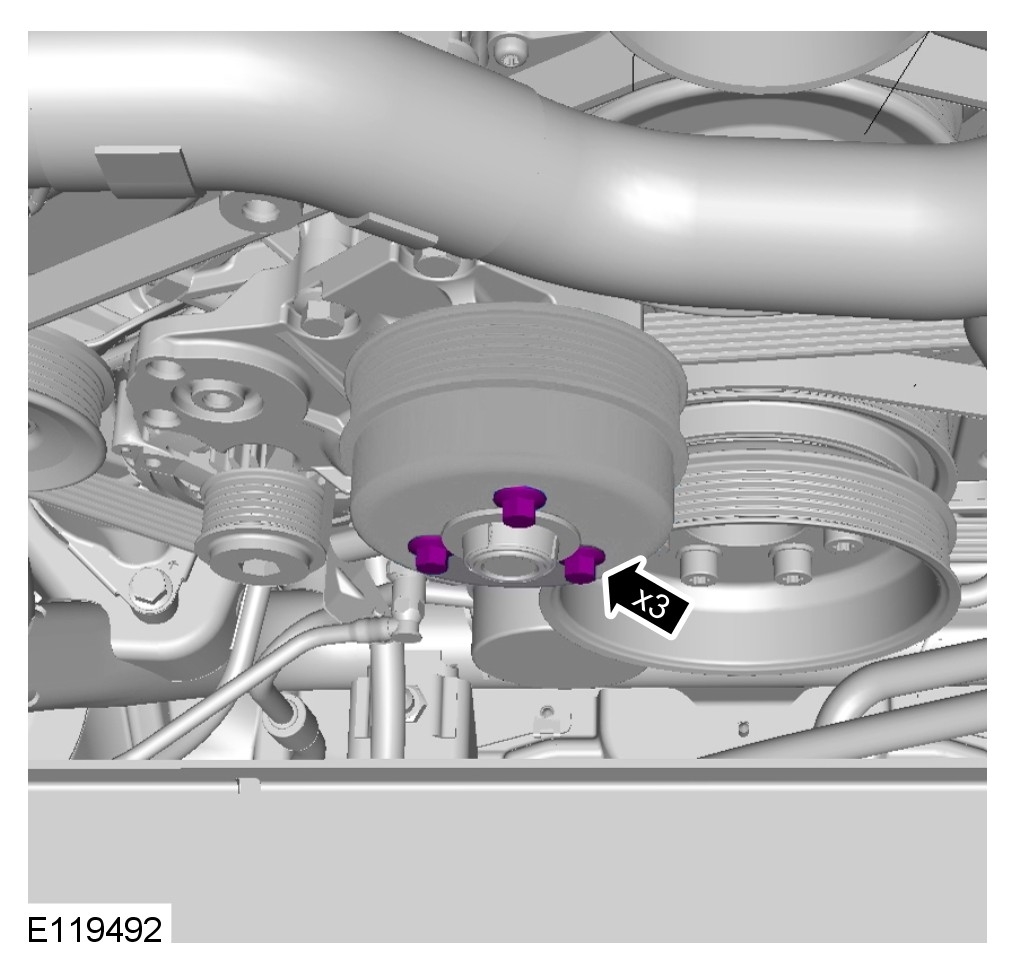
pic 4
pic 5
NOTE:
Note the fitted position.
pic 6
Installation
pic 7
Torque to: 25 Nm
pic 8
NOTE:
Note the fitted position.
pic 9
Torque to: 25 Nm
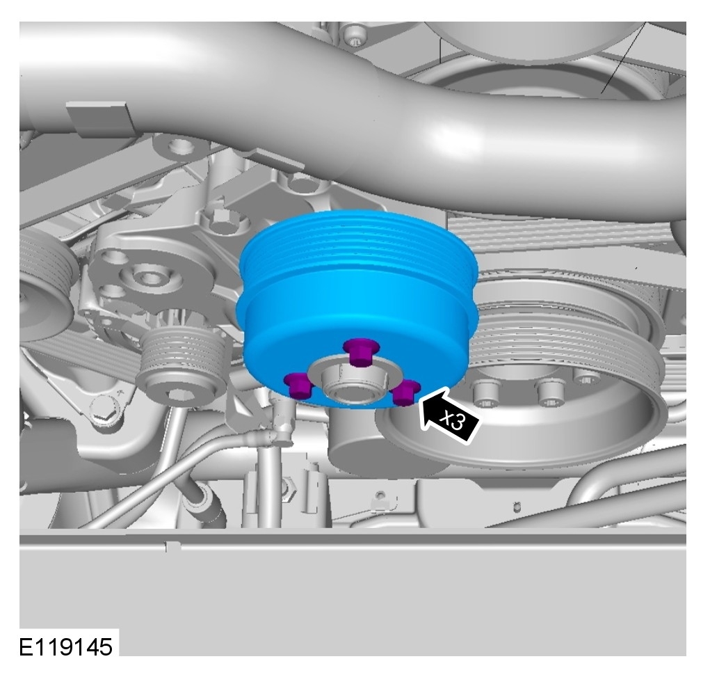
pic 10
Torque to: 25 Nm
pic 11
CAUTION: Always protect the cooling pack elements to prevent accidental damage.
NOTE:
The thread is right handed.
NOTE:
Some variation in the illustrations may occur, but the essential information is always correct.
Install the cooling fan.
Torque to: 65 Nm
Special Service Tool
pic 12
Viscous Coupling Wrench, 303-1142
Special Service Tool
pic 13
Viscous Coupling Holding Tool, 303-1143
For additional information, refer to Supercharger Belt See: Drive Belt > Removal and Replacement > Supercharger Belt
1 Connect the battery ground cable.
For additional information, refer to See: Battery > Procedures > Battery and Charging System
_____________________________________________
If it is only the fan belt you need to replace, here are the directions for that.
2010 Land Rover Range Rover (LM) V8-5.0L SC
Cooling Fan Belt
Vehicle Engine, Cooling and Exhaust Engine Drive Belts, Mounts, Brackets and Accessories Drive Belt Service and Repair Removal and Replacement Cooling Fan Belt
COOLING FAN BELT
Cooling Fan Belt
This is a "Trustmark Authoring Standards (TAS) Repair Procedure"
- TAS style procedures can be identified by steps that have no accompanying step text and the magenta color of the electrical connectors and fasteners such as nuts, bolts, clamps or clips.
- TAS removal and installation procedures use a sequence of color illustrations to indicate the order to be followed when removing/disassembling or installing/assembling a component.
- Many of the TAS procedures will have the installation information within the removal steps.
- The TAS color illustrations use a variety of symbols to indicate important details of the procedures. It is important to understand these symbols in order to properly used the TAS procedures.
Refer to How to Use TAS Procedures and TAS Symbol Glossary at Vehicle | Description and Operation for additional information on these TAS procedures.
For additional information, refer to How to Use TAS Procedures See: Vehicle > Components > How to Use TAS Procedures
Removal
1 Disconnect the battery ground cable.
For additional information, refer to See: Battery > Procedures > Battery and Charging System
For additional information, refer to Air Cleaner Outlet Pipe T-Connector
pic 14
CAUTION: Always protect the cooling pack elements to prevent accidental damage.
NOTE:
Some variation in the illustrations may occur, but the essential information is always correct.
Special Service Tool
pic 15
Viscous Coupling Wrench, 303-1142
Special Service Tool
pic 16
Viscous Coupling Holding Tool, 303-1143
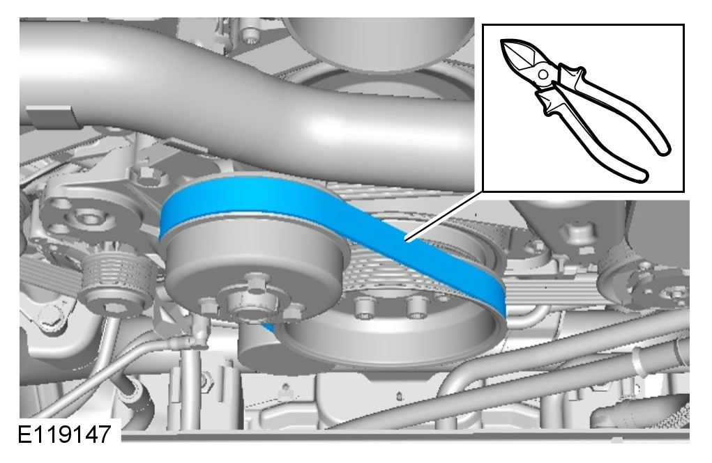
pic 17
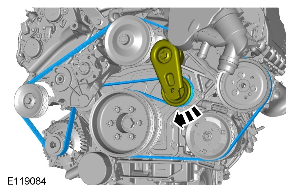
Installation
pic 18
Install the cooling fan belt.
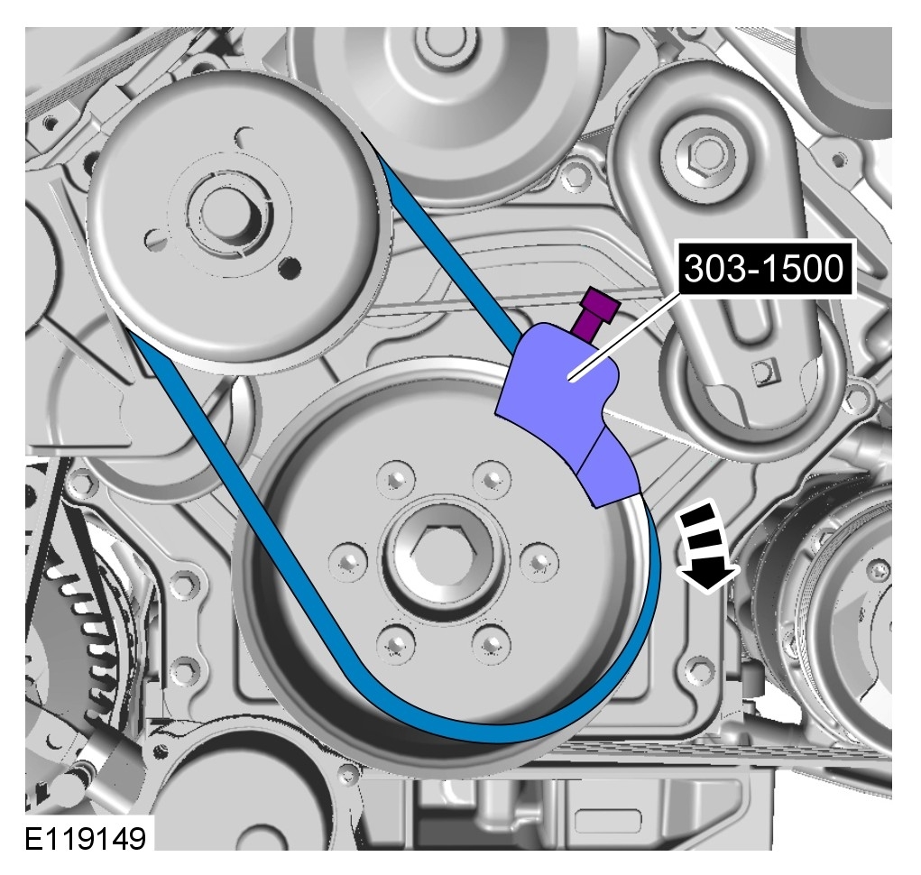
Special Service Tool
pic 19
Installer, Stretchy Belt, 303-1500
Whilst rotating the engine, make sure that pressure is applied to the left hand side of the cooling fan belt to aid installation.
Rotate the engine until the special tool has reached the 9 o clock position.
1 Remove the special tool.
2 Rotate the engine clockwise twice, making sure that the belt is seated on both pulleys correctly.
pic 20
CAUTION: Always protect the cooling pack elements to prevent accidental damage.
NOTE:
Some variation in the illustrations may occur, but the essential information is always correct.
Torque to: 65 Nm
Special Service Tool
pic 21
Viscous Coupling Wrench, 303-1142
Special Service Tool
pic 22
Viscous Coupling Holding Tool, 303-1143
For additional information, refer to Air Cleaner Outlet Pipe T-Connector
3 Connect the battery ground cable.
For additional information, refer to See: Battery > Procedures > Battery and Charging System
________________________________
Let me know if this helps or if you have other questions.
Take care,
Joe
Images (Click to enlarge)
Apr 20, 2020 at 9:42 PM