Neither is practical. If you're thinking about an '87 or newer GM generator, that is by far the worst design ever produced. It isn't going to mount to your engine. Their '86 and older was far more reliable, and in my opinion, the world's second-best design only to Chrysler's 1970 and newer system. Both GM units require a "Battery" light in the instrument cluster for the turn-on circuit.
That external regulator you referred to was the first electronic regulator, and while it is true, it will run your Nippendenso alternator, the Engine Computer will detect the lack of field current in that circuit, it will set a fault code for "field current not switching properly", and turn on the Check Engine light. With that light on, you'll never know when another problem is detected. That could be a very minor problem that can turn expensive when you ignore it because you don't know about it.
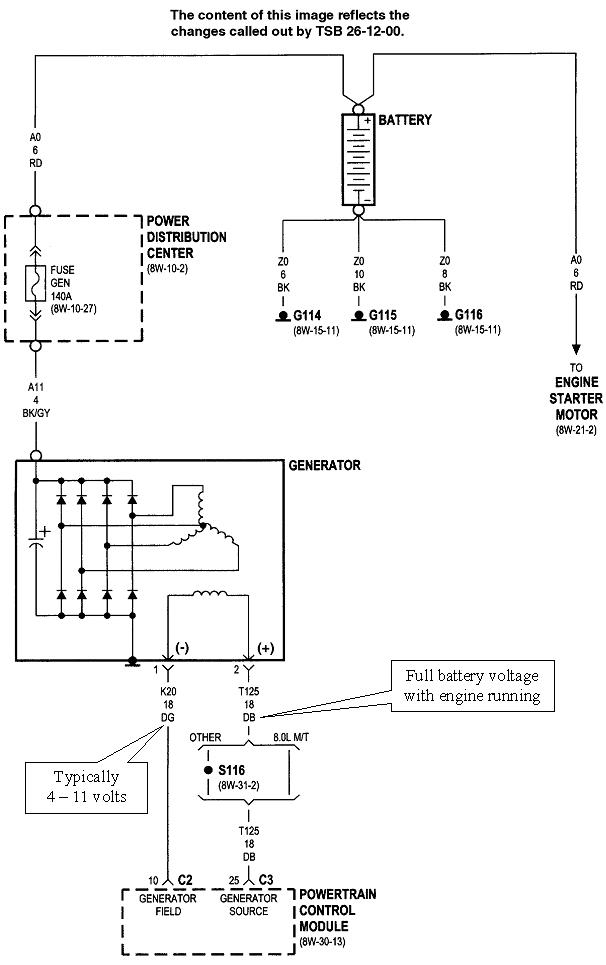
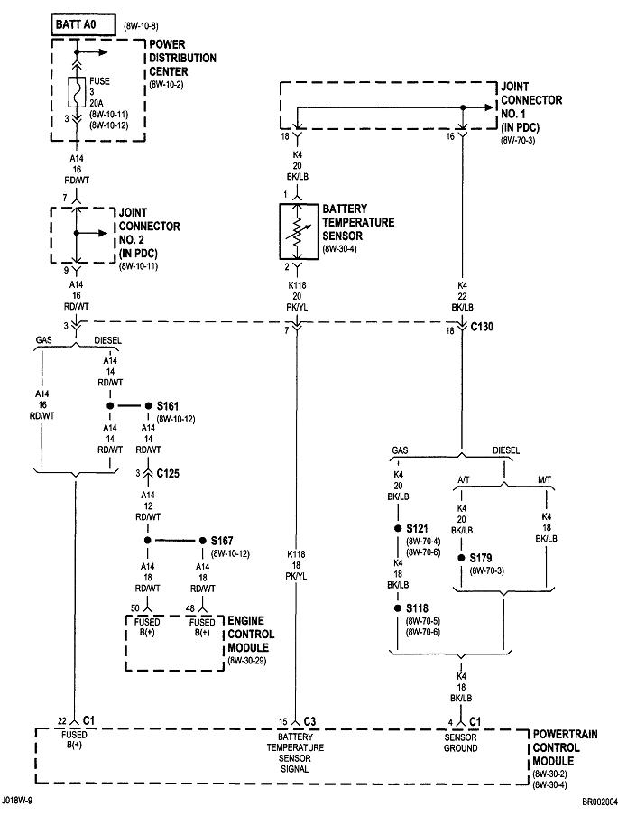
These circuits are uncommonly simple, and easy to diagnose. That is the only proper way to repair it. The entire circuit is shown in the first diagram. I included the second one for reference, but it isn't involved with this problem. The first step is to verify you have full battery voltage on the large black / gray wire bolted to the back of the alternator. Check that with the engine not running. If it is missing, the 140-amp fuse is blown or its bolts are loose. That is bolted into the under-hood fuse box.
Next, there's two wires plugged into the back of the alternator. For voltage readings to be valid, they have to be taken with that connector plugged in, and the engine must be running. Back-probe through the rubber seals around the wires. The dark blue wire must have full battery voltage. The dark green wire is the control circuit. It should have between about 4 - 11 volts. The lower this voltage is, the larger the difference between the two wires is, and the larger the electromagnetic field will be. The larger the magnetic field, the more output current will be developed.
By far the most common failure is worn brushes inside the alternator, then you'll find 0 volts on the dark green wire. Since you replaced the alternator already, the next most common failure is a break in the dark green wire. You'll also have 0 volts on it if it is shorted to ground, but then the symptom would be severe over-charging.
If you find exactly the same voltage on both of these smaller wires, the dark green wire is not being pulled to ground by the regulator circuit. The regulator circuit in the Engine Computer could be defective, but that is not a common failure. Before condemning the computer, measure the voltage on the dark green wire right at the computer's connector. If the dark green wire is okay, you'll still have full battery voltage at this terminal. If you find 0 volts at the computer's connector, but battery voltage at the alternator, that dark green wire has to have a break in it.
Images (Click to enlarge)
Jun 27, 2019 at 7:29 PM