Welcome to 2CarPros.
If you have spark and it still won't start for a couple seconds using starting fluid, I suspect there is an issue with timing or engine compression. Although the timing belt is there and turning the cams, they could be off time. That will result in lowered engine compression and a no start.
With that, the first thing I would do is check the engine compression. Here is a link that shows in general how it is done:
https://www.2carpros.com/articles/how-to-test-engine-compression
Here are the directions specific to your vehicle for testing compression. The manufacturer's specs are included in the directions. Also, the two attached pictures correlate with these directions.
________________________
2002 Mitsubishi Truck Montero Sport LTD 4WD V6-3.5L SOHC
Compression Pressure Check
Vehicle Powertrain Management Tune-up and Engine Performance Checks Compression Check Testing and Inspection Component Tests and General Diagnostics Compression Pressure Check
COMPRESSION PRESSURE CHECK
COMPRESSION PRESSURE CHECK
1. Before inspection, check that the engine oil, starter and battery are normal. Also, set the vehicle in the following condition:
^ Engine coolant temperature: 80 - 95°C (176 - 203°F)
^ Lights, and all accessories: OFF
^ Transmission: P range
2. Disconnect the spark plug cables.
3. Remove all of the spark plugs.
pic 1
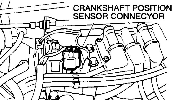
4. Disconnect the crankshaft position sensor connector.
NOTE: Doing this will prevent the powertrain control module from carrying out ignition and fuel injection.
WARNING: Keep your distance from file spark plug hole when cranking. Oil, fuel, etc., may spray out from the spark plug hole and may cause serious injury.
5. Cover the spark plug hole with a shop towel etc., during cranking. After the engine has been cranked, check for foreign material adhering to the shop towel.
pic 2
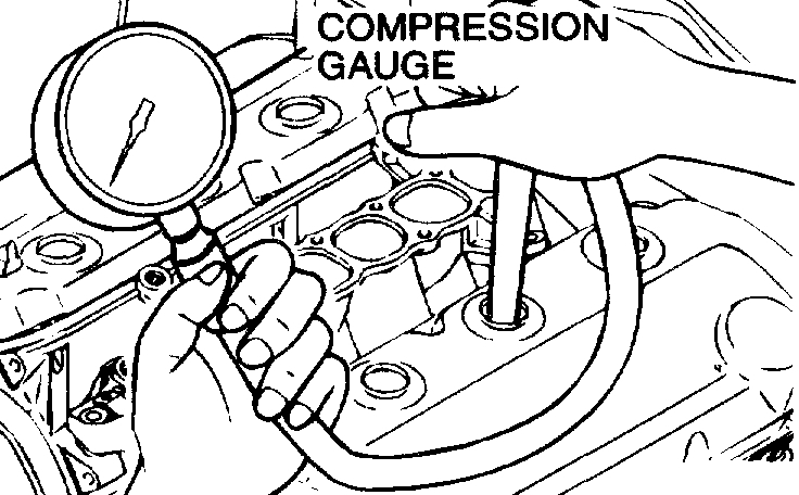
6. Set compression gauge to one of the spark plug holes.
7. Crank the engine with the throttle valve fully open and measure the compression pressure.
Standard value (at engine speed of 250 - 400 r/min): 1,200 kPa (171 psi)
Minimum limit (at engine speed of 250 - 400 r/min): 890 kPa (127 psi)
8. Measure the compression pressure for all the cylinders, and check that the pressure differences of the cylinders are below the limit.
Limit: 98 kPa (14 psi)
9. If there is a cylinder with compression or a compression difference that is outside the limit, pour a small amount of engine oil through the spark plug hole, and repeat the operations in steps 6 to 8.
1. If the compression increases after oil is added, the cause of the malfunction is a worn or damaged piston ring and/ or cylinder inner surface.
2. If the compression does not rise after oil is added, the cause is a burnt or defective valve seat, or pressure is leaking from the gasket.
10. Connect the crankshaft position sensor connector.
11. Install the spark plugs and spark plug cables.
12. Use the scan tool to erase the diagnostic trouble codes.
NOTE: This will erase the diagnostic trouble code resulting from the crankshaft position sensor connector being disconnected.
If you find the compression to be low, you will need to confirm the belt has not jumped time. I will provide the directions for belt replacement which includes timing mark locations and how to set timing.
_____________________________________
2002 Mitsubishi Truck Montero Sport LTD 4WD V6-3.5L SOHC
Removal and Replacement
Vehicle Engine, Cooling and Exhaust Engine Timing Components Timing Belt Service and Repair Removal and Replacement
REMOVAL AND REPLACEMENT
pic 3
pic 4
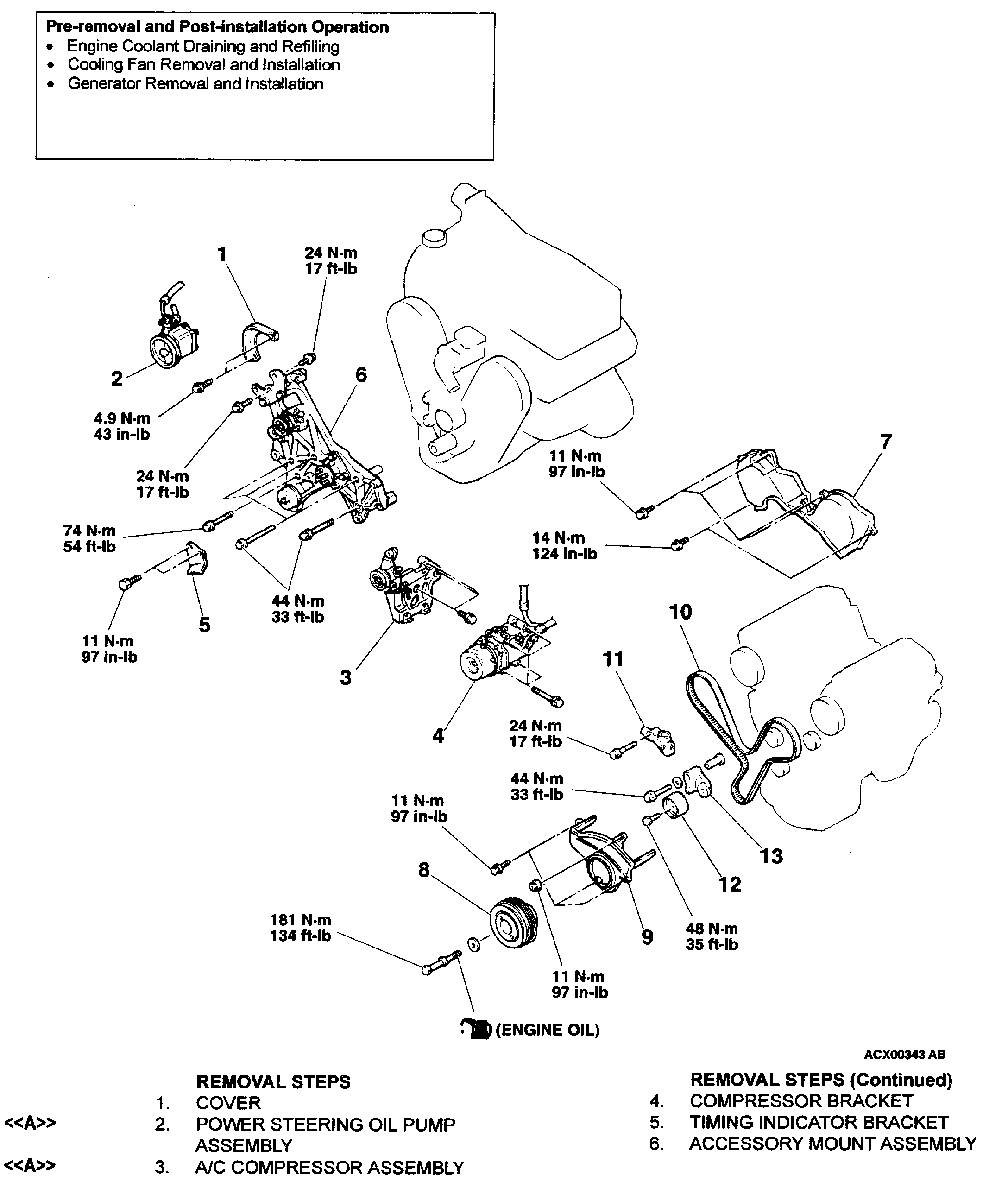
REMOVAL AND INSTALLATION
REMOVAL SERVICE POINTS
[[A]] POWER STEERING OIL PUMP ASSEMBLY / A/C COMPRESSOR ASSEMBLY REMOVAL
1. Do not disconnect the hoses to remove the pump and compressor.
2. Support the removed pump and compressor with a wire, etc. so that they will not get in the way while working.
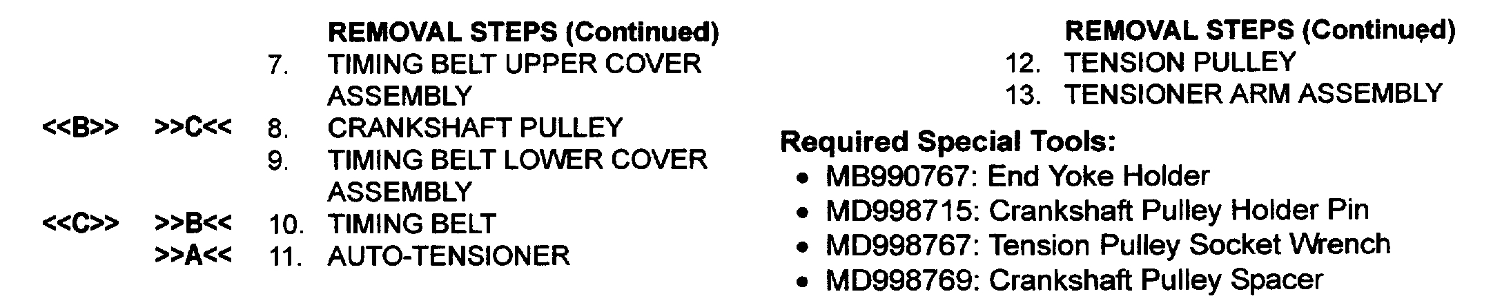
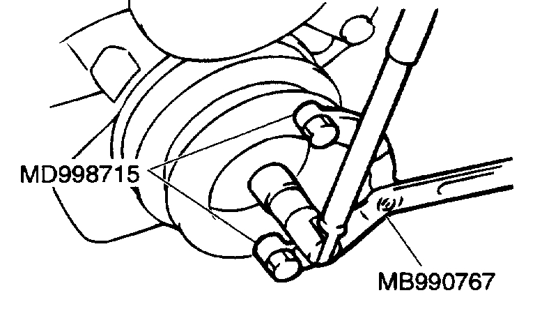
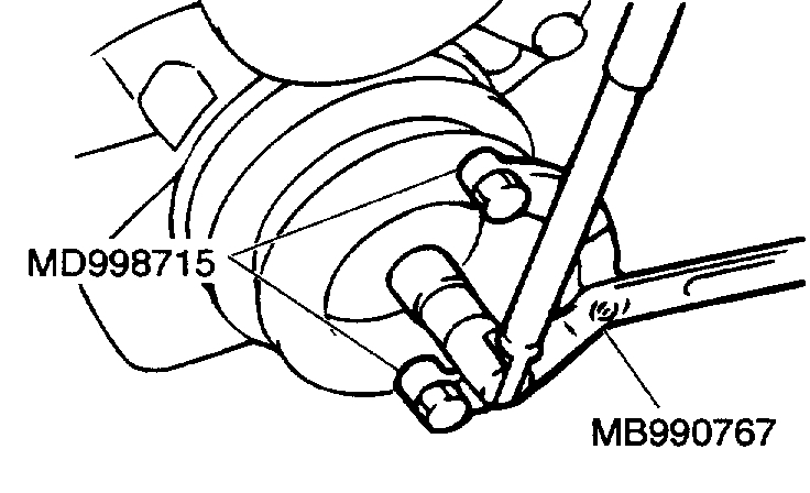
[[B]] CRANKSHAFT PULLEY REMOVAL
pic 5
Use special tools MD998715 and MB990767 to remove the crankshaft pulley from the crankshaft.
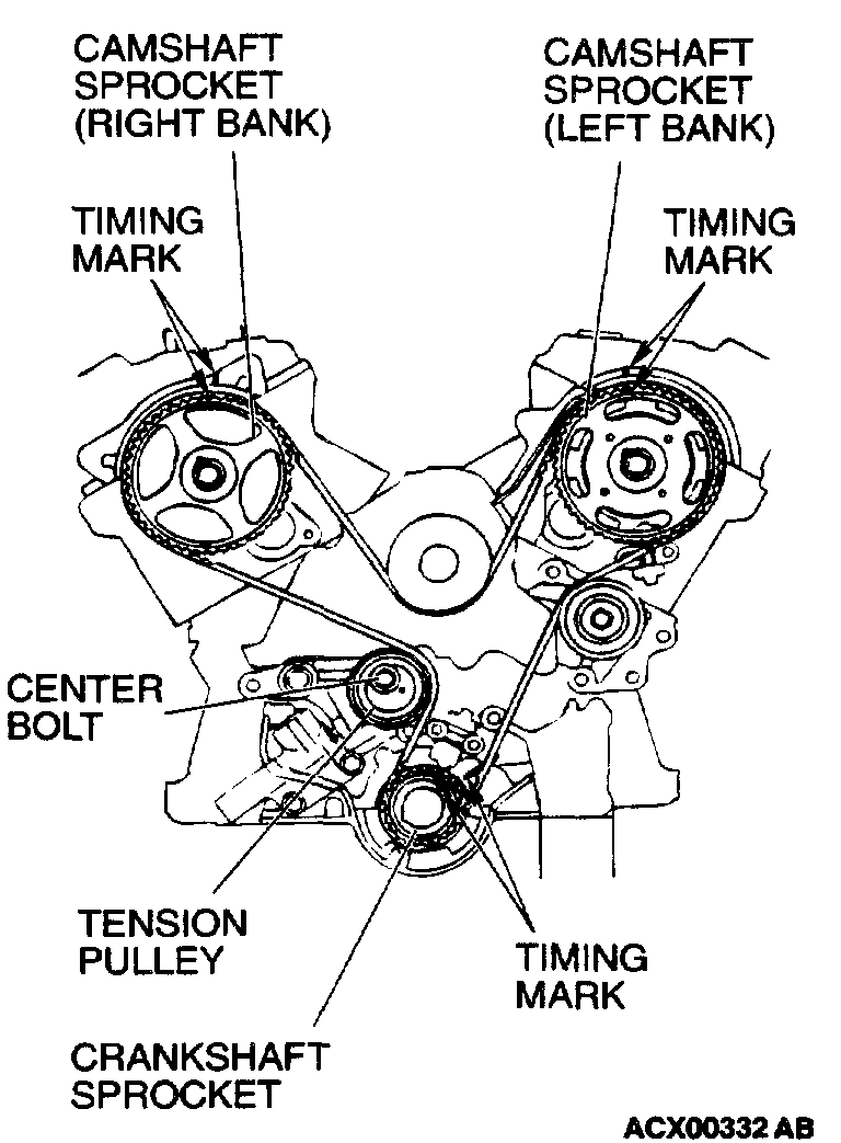
[[C]] TIMING BELT REMOVAL
CAUTION: Never turn the crankshaft counterclockwise.
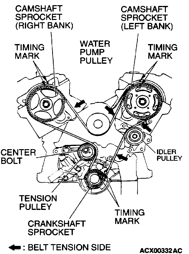
pic 6
1. Turn the crankshaft clockwise to align each timing mark and to set the number 1 cylinder to compression top dead center.
2. If the timing belt is to be reused, chalk mark the flat side of the belt with an arrow indicating the clockwise direction.
3. Loosen the center bolt of the tension pulley, and then remove the timing belt.
INSTALLATION SERVICE POINTS
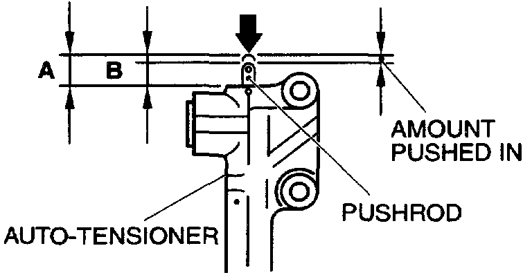
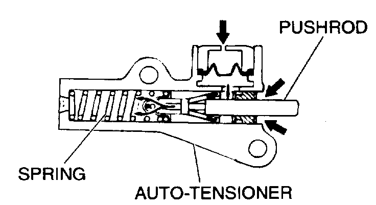
]]A[[ AUTO-TENSIONER INSTALLATION
pic 7
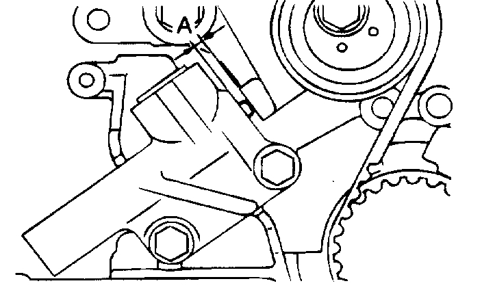
1. While holding the auto-tensioner by hand, press the end of the pushrod against a metal surface (such as the cylinder block) with a force of 98 - 196 Nm (72 - 145 ft. lbs.) and measure how far the pushrod is pushed in.
Standard value: Within 1 mm (0.04 inch)
A: Length when no force is applied
B: Length when force is applied
A - B: Amount pushed in
2. If it is not within the standard value, replace the auto tensioner.
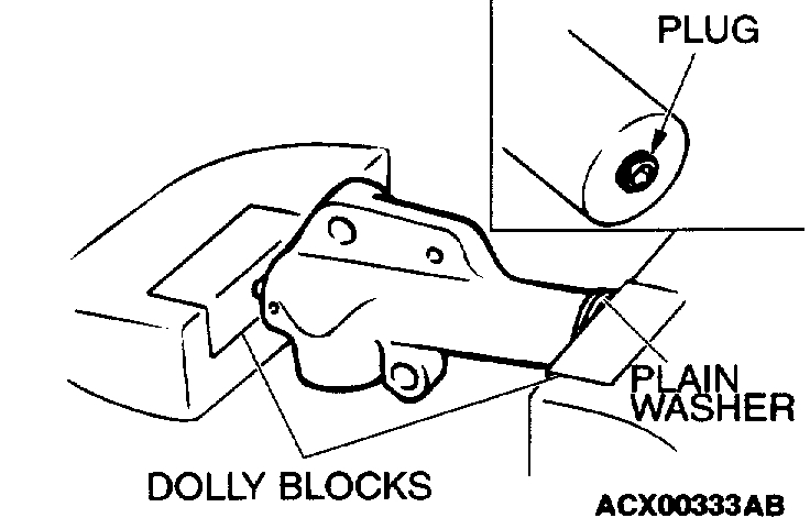
CAUTION:
^ Place the auto-tensioner perpendicular to the jaws of the vice.
^ If there is a plug at the base of the auto-tensioner, insert a plain washer onto the end of the auto-tensioner to protect the plug.
pic 8
3. Place two dolly blocks in a vice as shown in the illustration, and then place the auto-tensioner in the vice.
CAUTION: Never compress the pushrod too fast, or the pushrod may be damaged.
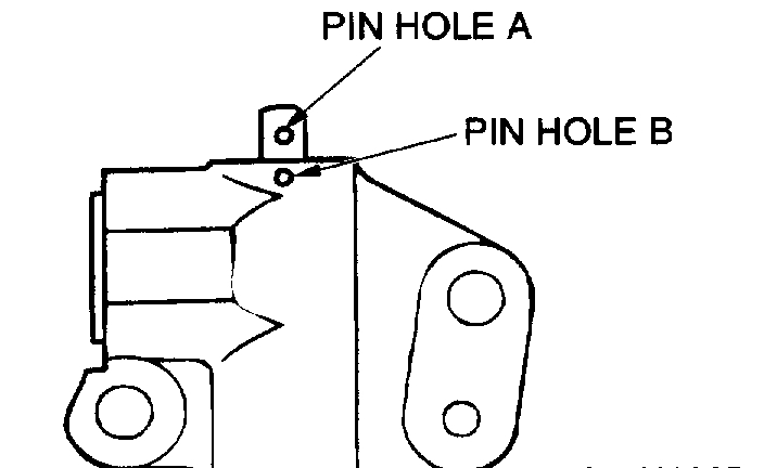
pic 9
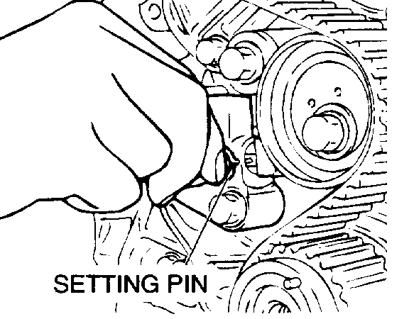
4. Slowly compress the pushrod of the auto-tensioner until pin hole A in the pushrod is aligned with pin hole B in the cylinder.
5. Insert the setting pin into the pin holes once they are aligned.
NOTE: If replacing the auto-tensioner, the pin will already be inserted into the pin holes of the new part.
CAUTION: Do not remove the setting pin from the auto-tensioner.
6. Install the auto-tensioner to the engine.
]]B[[ TIMING BELT INSTALLATION
1. Align the timing marks of the camshaft sprocket with those of crankshaft sprocket.
CAUTION: The camshaft sprocket (right side) can turn easily due to the spring force applied, so be careful not to get your fingers caught.
2. Install the timing belt by the following procedure so that there is no deflection in the timing belt between each sprocket and pulley.
1. Crankshaft sprocket
2. Idler pulley
3. Camshaft sprocket (Left side)
4. Water pump pulley
5. Camshaft sprocket (Right side)
6. Tension pulley
pic 10
3. Turn the camshaft sprocket counterclockwise until the tension side of the timing belt is firmly stretched. Check all timing marks again.
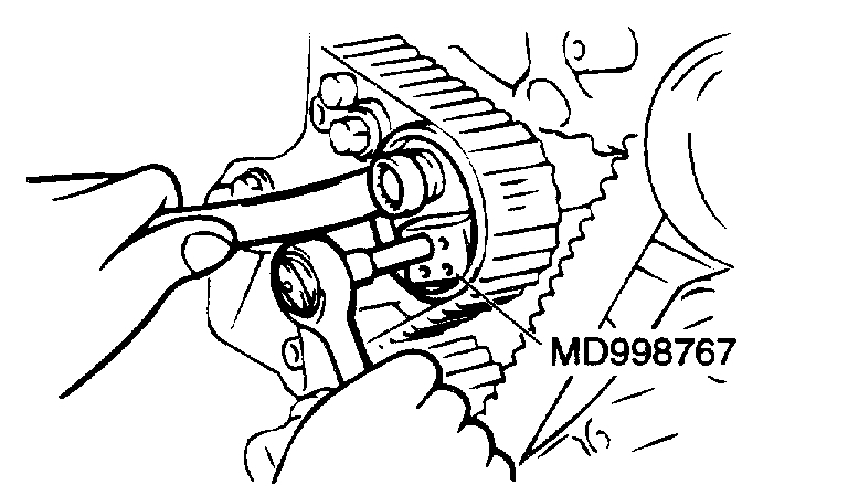
pic 11
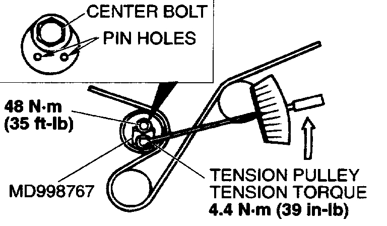
4. Use special tool MD998767 to push the tensioner pulley into the timing belt, and then temporarily tighten the center bolt.
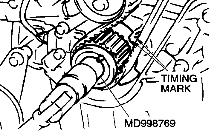
pic 12
5. Use special tool MD998769 to turn the crankshaft 1/4 turn counterclockwise and then turn it again clockwise until the timing marks are aligned.
CAUTION: When tightening the center bolt, be careful that the tensioner pulley does not turn with the bolt.
pic 13
6. Loosen the center bolt of the tensioner pulley. Use special tool MD998767 and a torque wrench to apply the standard torque to the timing belt as shown in the illustration. Then tighten the center bolt to the specified torque.
^ Standard value: 4.4 Nm (39 inch lbs.) [Timing belt tension torque]
^ Tightening torque: 48 Nm (35 ft. lbs.)
pic 14
7. Remove the setting pin that has been inserted into the auto-tensioner.
8. Turn the crankshaft two turns clockwise to align the timing marks.
9. Wait for at least five minutes, and then check that the auto-tensioner pushrod extends within the standard value.
Standard value (A): 3.8 - 5.0 mm (0.15 - 0.20 inch)
10. If no, repeat the operation in steps (5) to (9).
pic 15
11. Check again that the timing marks of each sprocket are aligned.
]]C[[ CRANKSHAFT PULLEY INSTALLATION
pic 16
Use special tools MD998715 and MB990767 to install the crankshaft pulley.
INSPECTION
AUTO-TENSIONER
pic 17
^ Check the auto-tensioner for possible leaks.
^ Check the pushrod for cracks.
____________________
Let me know if this helps or if you have other questions.
Take care,
Joe
Images (Click to enlarge)
Oct 4, 2019 at 7:28 PM