Hi,
I have to be honest. I can't imagine there is a difference as long as the new head is from the same year, make, model vehicle. They only offered one 1.3L on this vehicle and I just looked up cylinder head removal and there are no variations indicating there is a difference between a manual or automatic transmission.
The best you can do is simply confirm that it is the same visually. These were all SOHC engines, so you should be fine.
____________________________________________________________________________
Here are very basic directions just for cylinder head replacement. It provides torque specs and there is no indicator that the head bolts must be replaced. If the old ones are still good, you may want to consider reusing them. I looked just for curiosity, and found nothing as well. Ugh! That is so frustrating.
In addition to these directions, I added timing belt info. That is the one area most people ask for. I realize a lot of additional things need removed, if you need help with anything other, let me know. The second pic show torque sequence.
___________________________________________________________________________
1996 Ford Aspire L4-81 1.3L SOHC
Removal and Installation
Vehicle Engine, Cooling and Exhaust Engine Cylinder Head Assembly Service and Repair Procedures Removal and Installation
REMOVAL AND INSTALLATION
1. Disconnect battery ground cable, then drain engine coolant.
2. Remove timing belt covers and timing belt.
3. Remove rocker arm cover.
4. Remove intake manifold and exhaust manifold.
5. Disconnect spark plug wires and remove spark plugs from cylinder head.
6. Disconnect distributor electrical connections, scribe alignment marks on distributor base flange and cylinder head, then remove the distributor.
7. Remove front and rear engine lifting eyes, then disconnect ground wire from cylinder head.
8. Disconnect all remaining electrical wiring that will interfere with cylinder head removal.
9. Remove upper radiator hose, then the bypass hose and bracket.
10. Remove cylinder head attaching bolts, cylinder head and gasket.
11. Reverse procedure to install, noting the following:
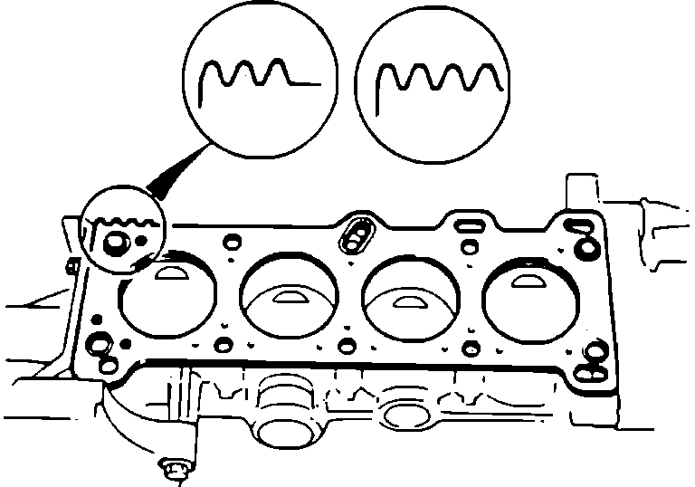
a. Ensure cylinder head and block mating surfaces are clean and free of gasket material.
Fig. 2 Positioning Head Gasket
pic 1
b. When installing head gasket, ensure serrated edges of gasket are positioned as shown.
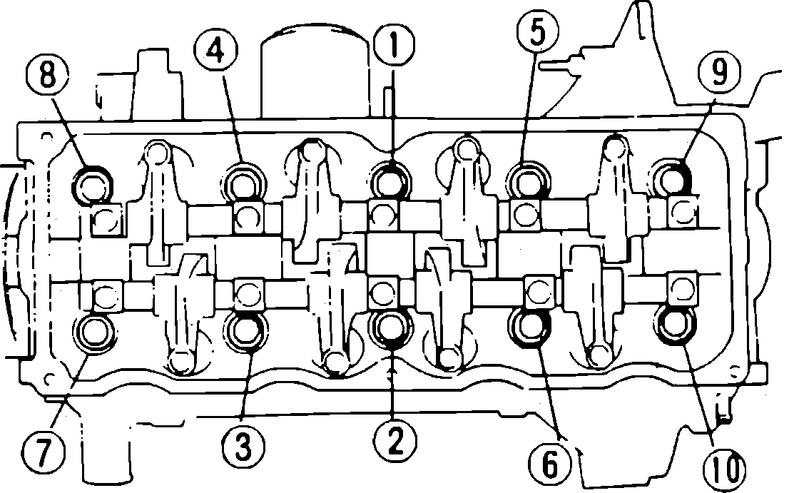
Fig. 3 Cylinder Head Bolt Tightening Sequence
pic 2
c. Tighten head bolts to 50-60 Nm (35-40 lb ft) in the sequence shown. Tighten again in the same sequence to 75-81 Nm (55-60 lb ft).
________________________________________________________________________________________
1996 Ford Aspire L4-81 1.3L SOHC
Procedures
Vehicle Engine, Cooling and Exhaust Engine Timing Components Timing Belt Service and Repair Procedures
PROCEDURES
1. Remove timing cover.
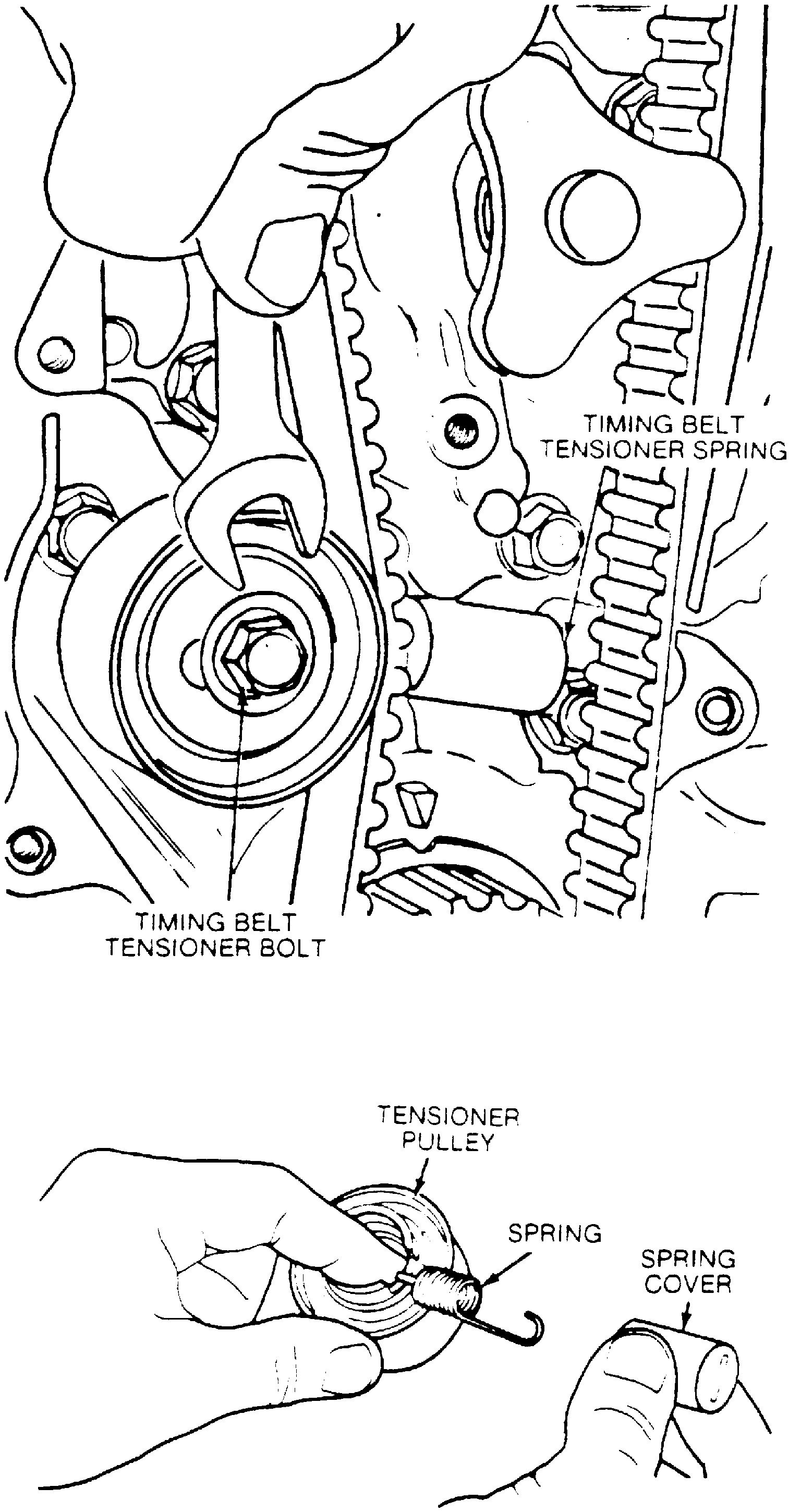
Fig. 11 Timing Belt Tensioner Assembly
pic 3
2. Remove timing belt tensioner pulley attaching bolt, then the tensioner pulley, spring and spring cover.
3. If reusing old belt, mark direction of rotation on belt to aid installation.
4. Remove timing belt from crankshaft and camshaft sprockets.
5. Check crankshaft and camshaft sprockets, tensioner pulley, and timing belt for wear or damage. Replace components as necessary.
Fig. 12 Valve Timing Mark Alignment
pic 4
6. Align camshaft and crankshaft sprocket timing marks with marks on cylinder head and oil pump housing.
7. Install timing belt. If reusing old belt, ensure belt is installed so that direction of rotation mark made during removal is positioned correctly.
8. Install spring and spring cover onto tensioner pulley, then install pulley and attaching bolt. Do not tighten bolt at this time.
9. Install tensioner spring onto anchor tightening pulley attaching bolt to 19-26 Nm (14-19 lb ft).
10. Time camshaft and crankshaft as follows:
a. Align crankshaft pulley timing notch with TC mark on timing belt cover tab.
b. Remove upper timing cover.
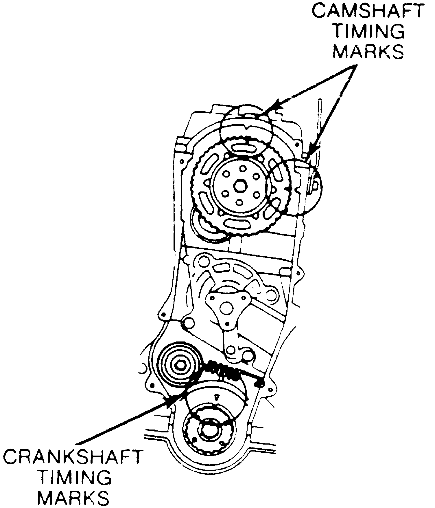
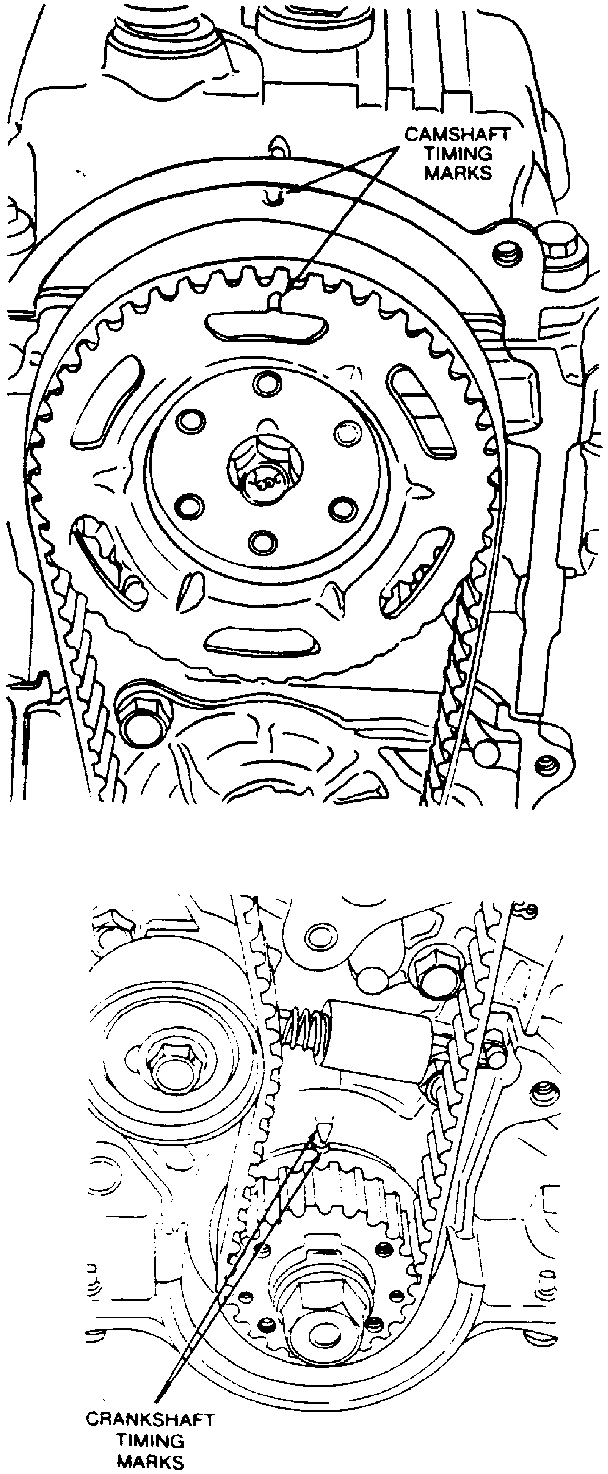
Fig. 13 Camshaft & Crankshaft Valve Timing Marks
pic 5
c. Camshaft timing marks should be aligned. If camshaft timing cannot be viewed, rotate crankshaft pulley one revolution, aligning notch with timing cover TC mark.
d. If camshaft timing marks are aligned, the camshaft is properly timed to the crankshaft.
11. Reinstall timing cover.
___________________________________________________________________________________
Let me know if this helps, if you need additional information, or if you just have questions.
Take care,
Joe
Images (Click to enlarge)
Apr 18, 2020 at 7:39 PM