Can I get the electrical wiring diagram for buttons on steering wheel and opening the door by kick?

Tiny
PAWEL_N
  • MEMBER
  • 2017 CHRYSLER PACIFICA
  • 3.6L
  • V6
  • 2WD
  • AUTOMATIC
  • 67,000 MILES
I did modification for EU regulations. I connected the front turn light 21W bulb with the rear turn light LED 4W and the right turn light turned off. I disconnected the rear light LED 4W and there was no turn light. I didn't use the car and after a few days I opened the door by remote and the turn light switched on. The turn light was working as okay. I replaced the front turn bulb 21W with LED 4W and connected rear turn LED 4W and all turn lights are working.

But, unfortunately, some buttons on steering wheel and opening the door by kick is not working!
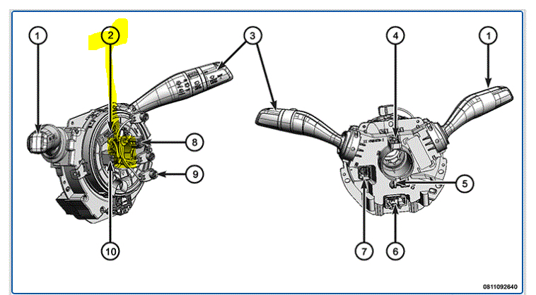
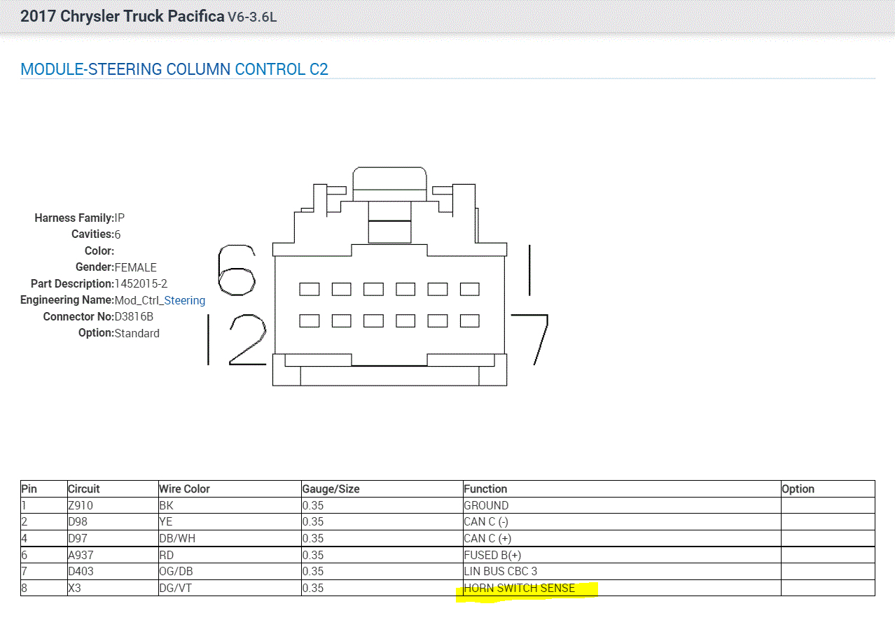
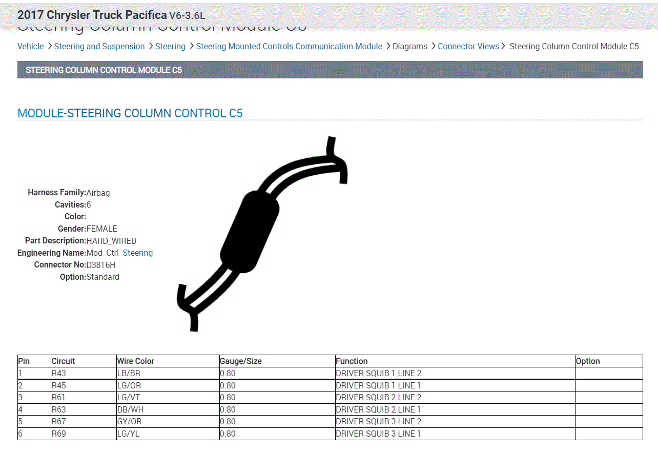
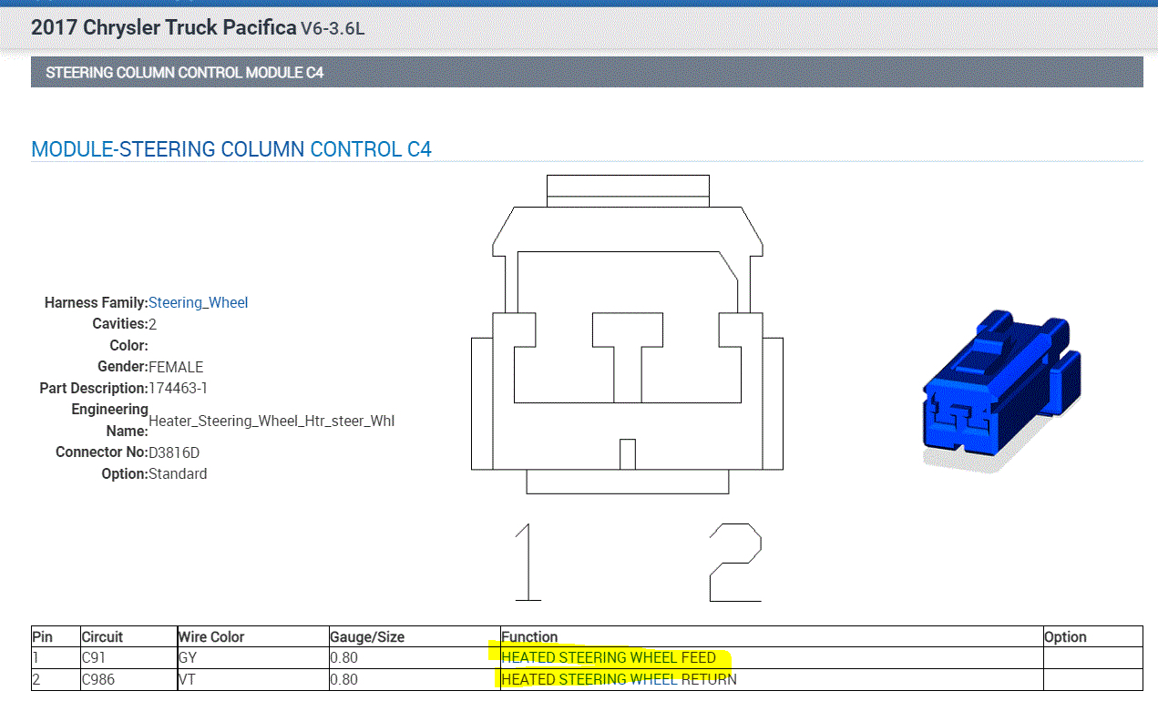
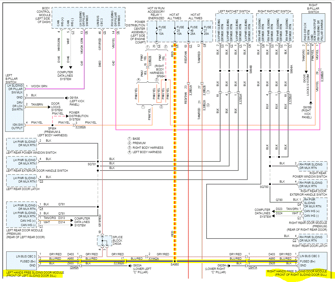
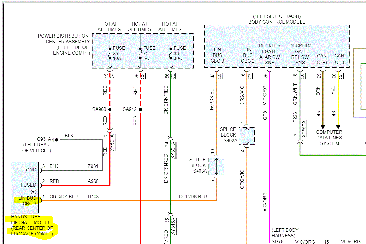
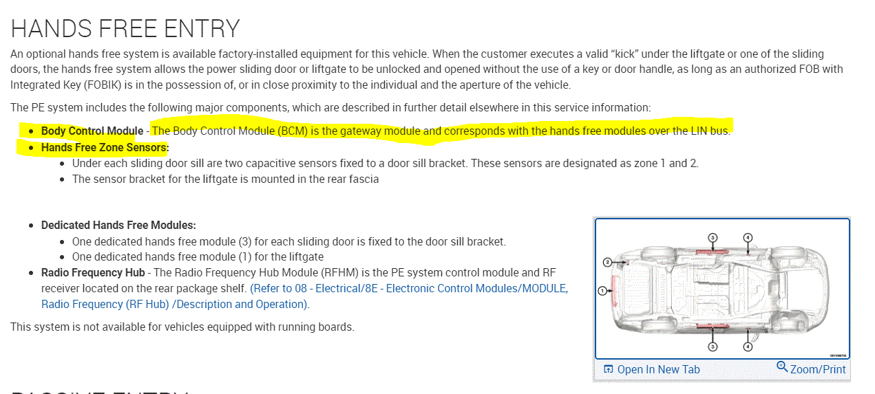
Do not work - steering wheel button's light, left buttons on steering wheel (8 pcs buttons), volume control and programs change on back steering wheel (cruise control is working), opening the sliding door and rear door by kick under door. I do not know if some other function is not working.

I don't know if my modifications for turn lights are something in common for disfunction of steering wheel and doors. Or the car stayed for a week during the rain, and something got wet and stopped working.

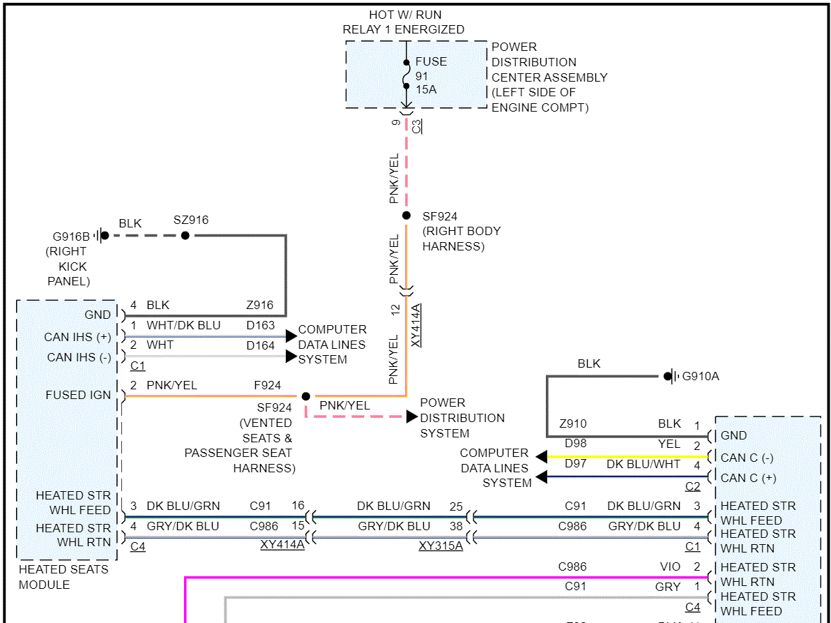
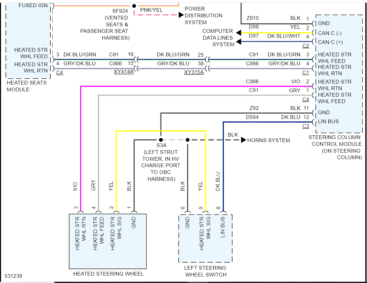
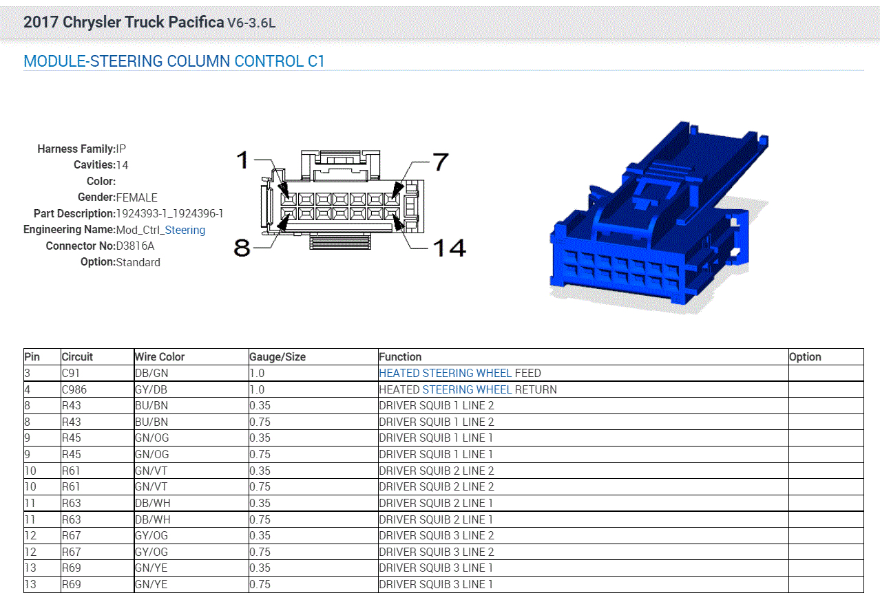
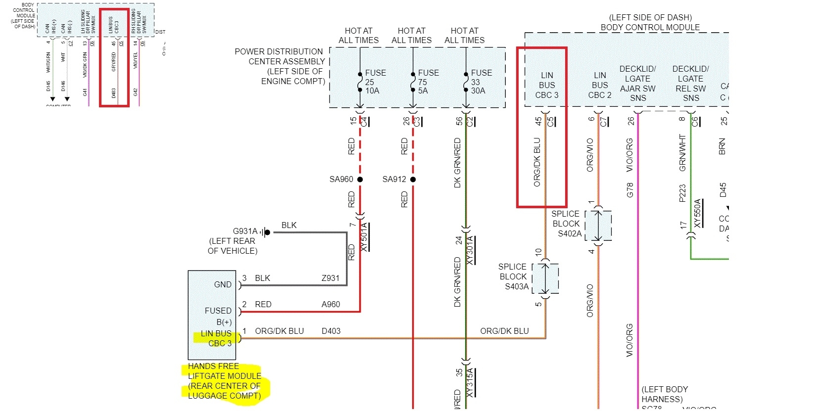
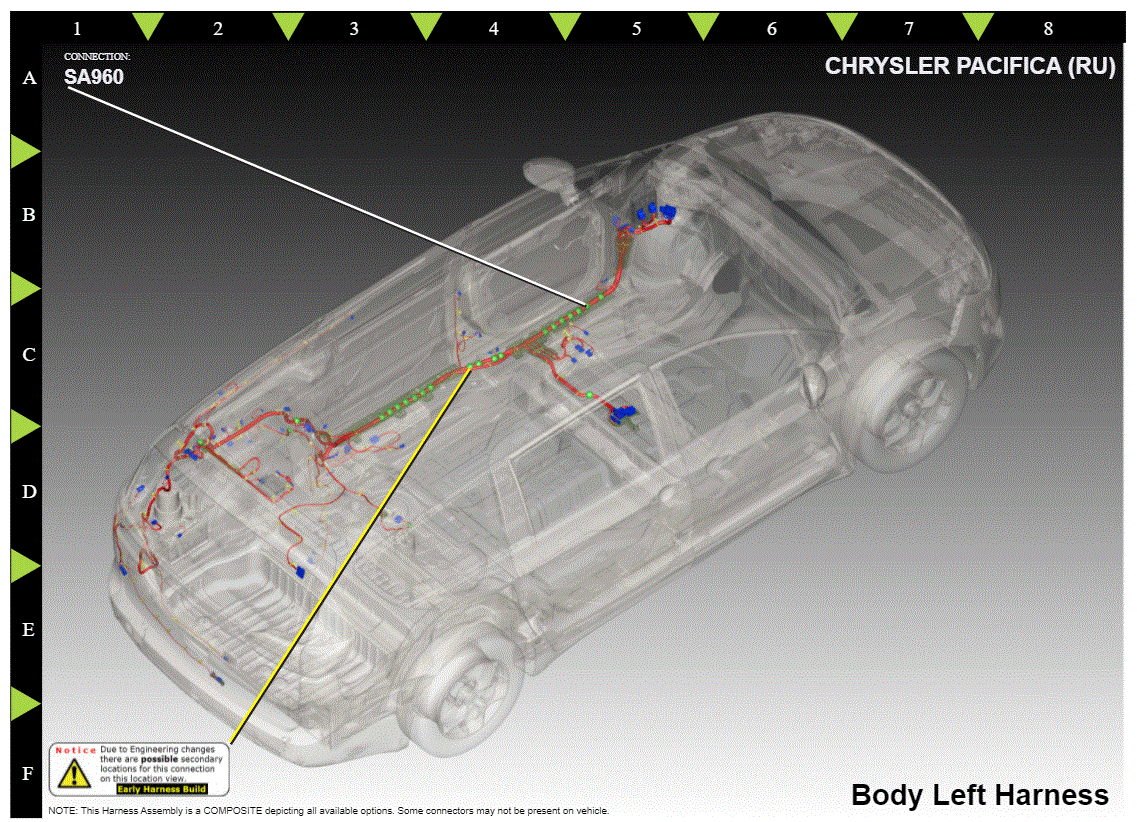
Could you please post wiring diagrams for these functions (I think it is communication/connections from /to steering wheel and comfort module for sliding and rear door.

Have a nice day,
Pawel
Friday, January 7th, 2022 AT 5:37 AM

15 Replies

Tiny
PAWEL_N
  • MEMBER
  • 167 POSTS
I checked BCM. It looked okay, I checked all fuses, and all was okay. But I got next faulty - the heating steering wheel this afternoon stopped working. It was working today morning (before fuses checking).
I need the heating steering wheel wiring too.
Was this
answer
helpful?
Yes
No
Friday, January 7th, 2022 AT 8:42 AM
Tiny
JACOBANDNICKOLAS
  • MECHANIC
  • 108,133 POSTS
Hi,

There is a steering column control module (SCCM) that may be causing issues. Also, as far as the heated steering wheel is concerned, I was able to find that schematic for you and attached it below. See pics 1 and 2.

The SCCM is responsible for the horn switch, the optional heated steering wheel, and the standard equipment Driver Airbag (DAB) are pass-through this circuit. The SCCM contains the clock spring (see pic 3) that, in this case, sounds like it failed. It also contains the steering angle sensor, so I'm not sure if there are issues with that.

At this point, I would recommend having the can-bus scanned to see if there is communication from the SCCM. If you have already done this, let me know if there were codes. Codes related to the SCCM are usually U type codes and not P.

The last 5 pics below are the connectors at the SCCM. Take a look through them and the legends included and see if it affects what you are having trouble with.

Let me know.

Take care,

Joe

See pics below.
Was this
answer
helpful?
Yes
No
+2
Friday, January 7th, 2022 AT 7:19 PM
Tiny
PAWEL_N
  • MEMBER
  • 167 POSTS
Thank you for your reply.
I don't have a problem with steering angle sensor now. I think about a new clock spring like first photo. But I am not sure about part number. Is it important which part number is it? Or it is no matter which model Pacifica is it?
And the second thing about hands free system for opening the sliding door and lift gate (rear door). Why do all doors stop working at the same time? How does the wiring diagram for hands free system?
Was this
answer
helpful?
Yes
No
Sunday, January 9th, 2022 AT 3:07 AM
Tiny
JACOBANDNICKOLAS
  • MECHANIC
  • 108,133 POSTS
Hi,

The clock spring is likely the same but take the part number from the old one to confirm. As far as the doors, there is a liftgate module, and sliding door modules.

Since the power comes back, we know it isn't a fuse even though they share the same one. Each module has a separate ground, so that isn't the issue. I suspect it has to do with the LIN-bus connection. LIN stands for local interconnect network. It is similar to the CAN-bus system but runs at a much slower speed and is usually used in body electronics. (See pics 1 and 2)

If you look at the two pics I provided, you will notice that each of the three modules communicate via LIN BUS CBC3. (Pics 1 and 2) Here is how it works, The LIN network is made up of one master node (module) and several slave nodes (modules). In this case, the slave nodes are the hands-free sliding door modules and liftgate. The master module (node) in this case is the body control module.

An easy way to check the LIN wiring is to unplug the slave module and check the †at rest’ voltage of the LIN wire. The master node should send approximately a 7v to 12v reference. If the wiring to the multi-function switch is good, the switch is likely bad.

I hope this makes sense. Since they all fail at once, the only thing tying them together is a fuse, which is very unlikely unless it is loose or corroded and the LIN-bus.

Take care,

Joe

See pics below. Pic 3 describes the BCM as the gateway and pic 4 shows the liftgate module. Pic 3 shows where the modules are located.
Was this
answer
helpful?
Yes
No
+2
Sunday, January 9th, 2022 AT 6:42 PM
Tiny
PAWEL_N
  • MEMBER
  • 167 POSTS
Hi Joe,

Thank you for your reply.
I do not understand the name of socket on BCM. For eg. - There is description socket C and pin 45 for this socket (second pic). It is the wire for LIN BUS CBC3. But on BCM housing the socket C has only 4 pin (first pic)! Where is pin 45 on C5 socket?
Was this
answer
helpful?
Yes
No
Monday, January 10th, 2022 AT 1:10 AM
Tiny
JACOBANDNICKOLAS
  • MECHANIC
  • 108,133 POSTS
Hi,

You are looking for connector c/e. If you look at the pics below, I circled and indicates what the plug looks like.

Let me know if this helps.

Joe

See pics
Was this
answer
helpful?
Yes
No
+2
Monday, January 10th, 2022 AT 3:32 PM
Tiny
PAWEL_N
  • MEMBER
  • 167 POSTS
I was in the car service today for scan tools diagnose and SCCM and clock spring is 100% OK. There is permanent fault U1045-00, it is LIN BUS3 error, as permanent/stable. It is the reason why do not working some buttons on steering wheel and hands free system for sliding and rear door. Probably there is faulty one hands free module or wires. I have to disconnect all or one by one hand free module for all 3 door and check if buttons on steering wheel start working.
1. I would like to ask you for wiring diagrams for sliding doors HF Modules and lift gate HF Module (rear door). I wold like to check continuity of wires and I would like to know where is palced wire harness for all HFM (from BCM to each HFM).
2. Schematics/wiring diagrams for all connections/wires with pin 45 (LIN BUS CBC3) on C5 socket on BCM and pin 15 (power supply for HFM) on Power Distribution Center Assembly.
3. And where is Splice Block D403A located/situated? There are pin 3, 4, 5 use for 3xHF doors and pin 10 as source for BCM. Is there other modules for pin 1, 2, 6, 7, 8 and 9 used?
The last number of my car VIN is HR778803 (2017 year).
Thank you :-)
Was this
answer
helpful?
Yes
No
Tuesday, January 11th, 2022 AT 3:51 AM
Tiny
JACOBANDNICKOLAS
  • MECHANIC
  • 108,133 POSTS
Hi,

To get you started, I attached the location and pinout for the splice. That is where I would recommend starting.

Let me know.

Joe
Was this
answer
helpful?
Yes
No
+2
Tuesday, January 11th, 2022 AT 7:30 PM
Tiny
PAWEL_N
  • MEMBER
  • 167 POSTS
Thank you for your reply, Joe. It is a great diagram. I did not know that there are so many items connected to LIN interface.
I cannot find this place for D403A (Splice Block). It is not located inside car (not a red dot - my first picture on Paint :-)), under carpet (brown line), above steel/body. It is probably under body (blue line, green dot). How I can find this place?
Was this
answer
helpful?
Yes
No
Wednesday, January 12th, 2022 AT 4:47 AM
Tiny
PAWEL_N
  • MEMBER
  • 167 POSTS
I found it :-)
It is inside the car, above tire pump, left side of rear inside (the first photo).
But where is located the point/junction SA960?
I found the error about colors. The second picture - there is LINBUS3 wire pin 45 C5, once GRY/red and once ORG/BLU on BCM. You added on January 9th this picture before for sliding door and liftgate. Why there are two colors?
Was this
answer
helpful?
Yes
No
Wednesday, January 12th, 2022 AT 6:03 AM
Tiny
JACOBANDNICKOLAS
  • MECHANIC
  • 108,133 POSTS
Hi,

The wire colors could be due to a production date. It may have been built really early or really late which can cause change.

As far as SA960, it's under the kick plate at the driver's door. I attached a pic below showing its location.

Let me know if this helps

Take care,

Joe

See pic below.
Was this
answer
helpful?
Yes
No
+1
Wednesday, January 12th, 2022 AT 6:51 PM
Tiny
PAWEL_N
  • MEMBER
  • 167 POSTS
I found probably the reason for problems - there was a faulty junction/connection by left HF door module. I disconnected D403A for left HFDM and all buttons and the light on the steering wheel started working yesterday. HFDMR I HFLGM start working (without HFDML) too. I cleaned the junction by HFDML - it was dirty. I connected it but no HF door is working now (steering wheel is okay). It looks like a problem with HFDML. I need more time to check it again.
Thank you for your help :-)
Was this
answer
helpful?
Yes
No
Friday, January 14th, 2022 AT 6:46 AM
Tiny
JACOBANDNICKOLAS
  • MECHANIC
  • 108,133 POSTS
Hi,

You are very welcome. I'm interested in hearing what you find, so thanks for the update. It seems connector pins are getting smaller to add more of them. The result is this type of issue.

Take care of yourself and let me know if you have questions.

Joe
Was this
answer
helpful?
Yes
No
Friday, January 14th, 2022 AT 7:24 PM
Tiny
PAWEL_N
  • MEMBER
  • 167 POSTS
I found it - When I cleaned the junction by HFDML (it was dirty) I connect by accident junction GND and supply 12V together. And the fuse for sliding doors and lift gate was broken. It was so easy, and it take a lot of time.
Thank you for your help.
Was this
answer
helpful?
Yes
No
Thursday, March 24th, 2022 AT 5:00 AM
Tiny
JACOBANDNICKOLAS
  • MECHANIC
  • 108,133 POSTS
Hi,

First, you are very welcome. And thank you for the update. I'm glad to know you got it fixed.

Please feel free to come back anytime in the future if you have questions. You are always welcome.

Take care,

Joe
Was this
answer
helpful?
Yes
No
Thursday, March 24th, 2022 AT 7:16 PM

Please login or register to post a reply.

Sponsored links