Hi,
By chance is the engine light staying on when the engine is running? If so, you should scan the computer for codes. Here is a quick video showing how it's done:
https://youtu.be/YV3TRZwer8k
I realize most people don't own a scanner, but often times a parts store will do it free of charge. Have that done if that is the case.
Next, I suspect that something was loosened or damaged when the manifold gasket was replaced. Have you checked to confirm that no sensors are loose and there were no vacuum leaks. I am going to provide the directions for removal and replacement of the gasket. Take a look through it to make sure there was nothing you may have missed. Also, all the torque specs are included. The attached pics correlate with the directions.
___________________________________________
2001 Saturn SC1 L4-1.9L SOHC VIN 8
Intake Manifold Replacement
Vehicle Engine, Cooling and Exhaust Engine Intake Manifold Service and Repair Removal and Replacement Intake Manifold Replacement
INTAKE MANIFOLD REPLACEMENT
INTAKE MANIFOLD
REMOVAL
CAUTION: DO NOT ALLOW SMOKING OR THE USE OF OPEN FLAMES IN THE AREA WHERE WORK ON THE FUEL SYSTEM IS TAKING PLACE. ANYTIME THE FUEL SYSTEM IS BEING WORKED ON, DISCONNECT THE NEGATIVE BATTERY CABLE, EXCEPT FOR THOSE TESTS WHERE BATTERY VOLTAGE IS REQUIRED.
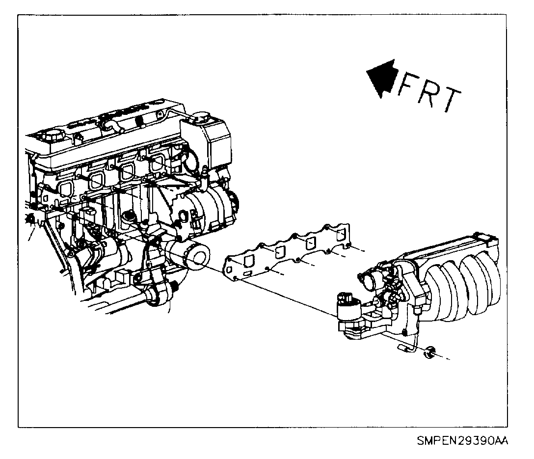
[pic 1
1. Disconnect negative battery terminal.
2. Drain engine coolant. Refer to "Engine Coolant Check and Replacement" in the Cooling System.
3. Remove air inlet tube and air filter cover, disconnecting fresh air hose at cam cover.
4. Remove PCV valve hose.
CAUTION: WHENEVER FUEL LINE FITTINGS ARE LOOSENED OR DISCONNECTED, WRAP A SHOP CLOTH AROUND FITTING WHILE CONNECTING GAUGE, TO COLLECT FUEL. PLACE THE CLOTH IN AN APPROVED CONTAINER.
5. Relieve fuel system pressure. Refer to "Relieving Fuel Pressure" in the Fuel System.
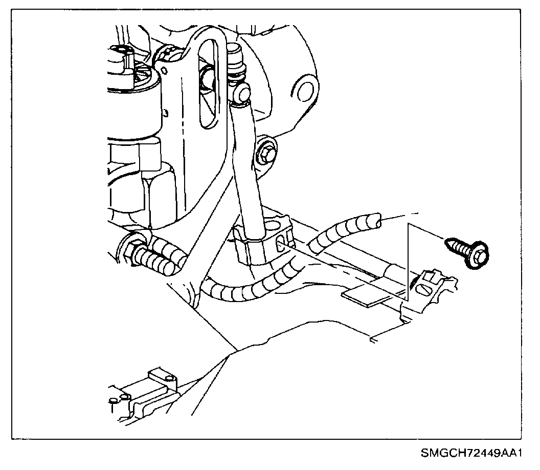
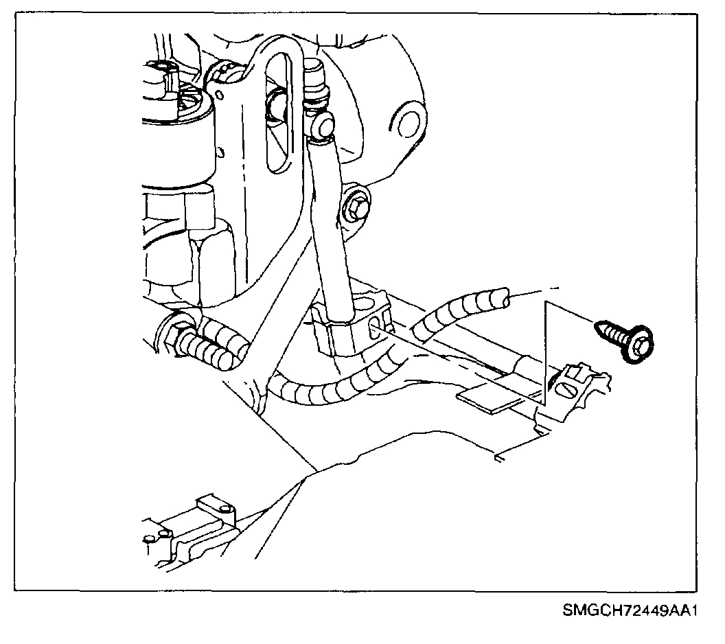
pic 2
6. Remove screw from fuel line clip and disconnect fuel line from rail.
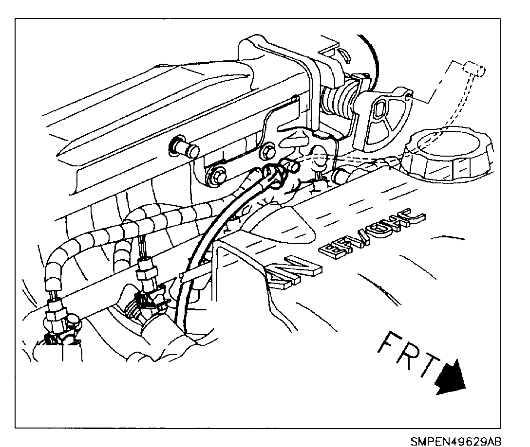
pic 3
7. Disconnect throttle cable from throttle body.
8. Remove throttle cable bracket attaching nuts.
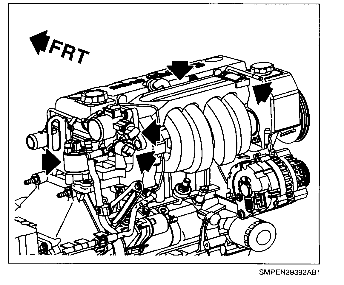
pic 4
9. Remove the following electrical connectors and harness wiring:
- Fuel Injectors
- Throttle position (TP) sensor
- Idle air control (IAC)
- Manifold absolute pressure (MAP) sensor
- EGR valve
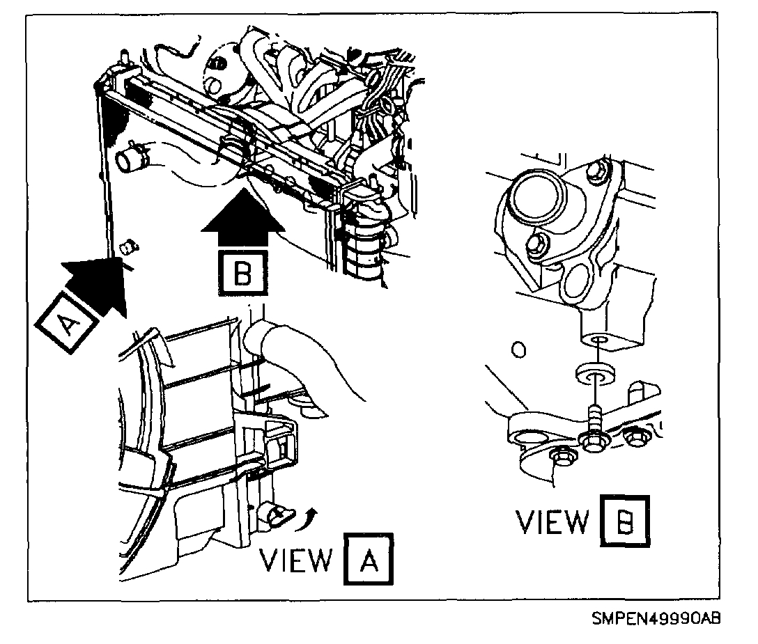
10. Disconnect heater and hose at intake manifold outlet.
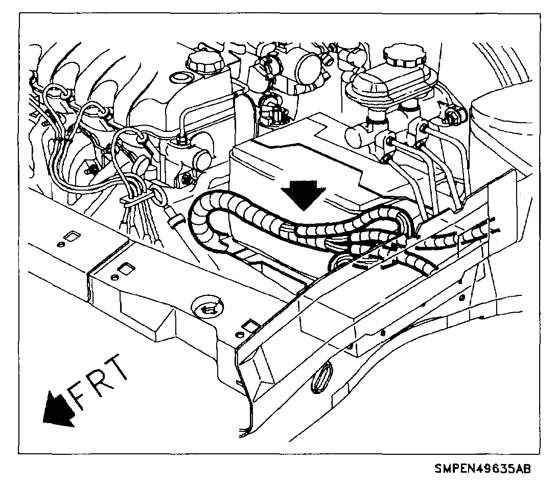
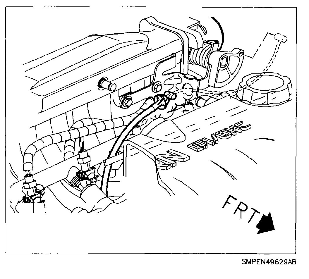
pic 5
11. Lay harness over brake master cylinder.
12. Remove the intake manifold support bracket bolt attached to the intake manifold located below the throttle body.
IMPORTANT: Label vacuum lines to make sure they are replaced properly.
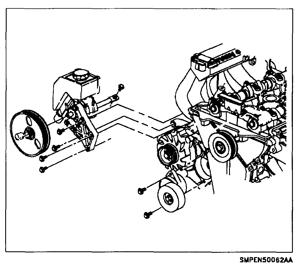
pic 6
13. Remove accessory drive belt.
14. Remove power steering pump assembly. Remove power steering pump bracket attachment bolts and position pump next to the right-hand front of dash panel, away from the cylinder head and intake manifold.
15. Remove the four upper intake manifold attachment nuts.
CAUTION: MAKE SURE VEHICLE IS PROPERLY SUPPORTED AND SQUARELY POSITIONED. TO HELP AVOID PERSONAL INJURY WHEN A VEHICLE IS ON A HOIST, PROVIDE ADDITIONAL SUPPORT FOR THE VEHICLE ON THE OPPOSITE END FROM WHICH COMPONENTS ARE BEING REMOVED. MAKE SURE HOIST DOES NOT CONTACT FUEL OR BRAKE LINES.
16. Raise vehicle.
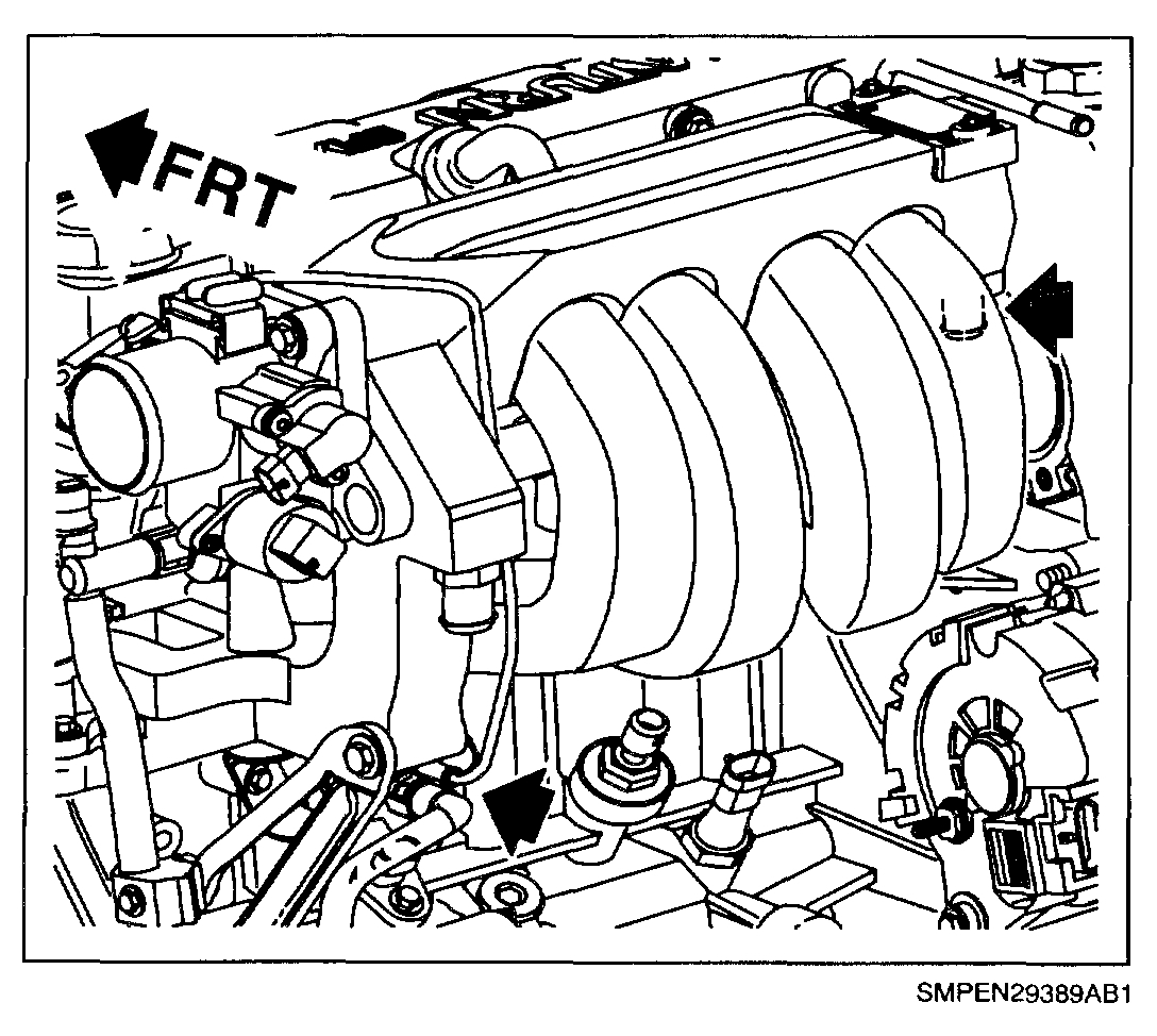
pic 7
17. Disconnect vacuum hose at the EVAP canister purge solenoid and brake booster.
pic 8
18. Remove 5 lower intake manifold attaching nuts.
19. Lower vehicle to floor.
20. Remove intake manifold assembly.
21. Remove intake manifold gasket and discard. Clean cylinder head and intake manifold gasket sealing surfaces. Inspect surfaces as outlines in the "SOHC (L24) Cylinder Head".
IMPORTANT: Clean and inspect cylinder head and intake manifold aluminum surfaces as outlined on the SOHC (L24: engine cylinder head.
INSTALLATION
IMPORTANT: Make sure cylinder head and air intake manifold gasket sealing surfaces is clean. Refer to "SOHC (L24) Cylinder Head" section for inspection requirements. Use Saturn P/N 21485276 Loctite 290(R) (or equivalent) to seal a PCV valve inlet tube into the manifold if replaced.
1. Install new intake manifold gasket.
2. Install intake manifold onto attaching studs.
3. Install intake manifold attaching nuts.
4. In sequence, torque the intake manifold attaching nuts.
Torque:
Intake Manifold-to-Head (L24): 30 N.m (22 ft-lbs)
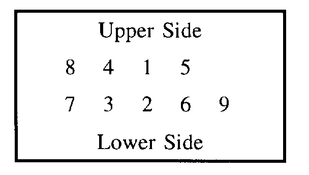
pic 9
Intake manifold bolt tightening sequence:
5. Install power steering pump assembly. Refer to Power Steering Pump" installation procedure in the steering section of the Chassis.
Torque:
Power Steering Pump-to-Bracket: 30 N.m (22 ft-lbs)
6. Install accessory drive belt. Make sure belt is properly aligned on the pulleys.
7. Connect the heater hose at intake manifold outlets. Make sure it is firmly seated.
CAUTION: WHENEVER FUEL LINE CONNECTORS ARE DISCONNECTED, LUBRICATE STEEL LINE MALE ENDS WITH CLEAN ENGINE OIL. HOLDING STEEL LINE, FIRMLY PRESS ON FEMALE COUPLER UNTIL A CLICK IS HEARD, THEN PULL BACK TO CONFIRM ENGAGEMENT. MAKE SURE THE FUEL LINE CONNECTS ARE FULLY SEATED. PINCHED, KINKED OR DAMAGED FUEL LINES MUST BE REPLACED.
NOTE: Replace plastic fuel retainer whenever the fuel supply is disconnect at the fuel rail. Install the new retainer into the female cavity of the connection. Care must be taken to assure that the locking tab is centered in the window of the female cavity. Firmly press the female connection onto the male end until a click is heard, then pull back to confirm engagement. Pinched, kinked, or damaged fuel lines must be replaced.
pic 10
8. Connect fuel supply line and fasten fuel line clip to brace.
Torque:
Fuel Line Retainer Clip: 4 N.m (35 in-lbs)
IMPORTANT: When the throttle cable is removed, make sure the locking tangs are fully engaged when assembled if disconnected.
pic 11
9. Connect throttle cable to throttle body, and throttle cable support bracket. Attach the accelerator control cable bracket.
Torque:
Accelerator Control Cable Bracket-to-Intake Manifold (L24): 30 N.m (22 ft-lbs)
IMPORTANT: Make sure to confirm positive engagement of electrical connectors and vacuum hoses.
10. Install the following electrical harness connectors and vacuum hoses.
10.1 Electrical connectors:
- Idle air control (IAC)
- Throttle position (TP) Sensor
- Manifold absolute pressure (MAP) Sensor
- Fuel injectors (4)
- EGR
10.2 Vacuum Hoses:
- EVAP canister purge solenoid
pic 12
11. Install PCV hose.
12. Install air inlet tube, fresh air hose, and air filter cover.
13. Connect negative battery terminal.
Torque:
Battery Terminal Bolts: 17 N.m (13 ft-lbs)
14. With engine off and ignition on, pressurize the fuel system and check for fuel leaks.
15. Install cylinder block drain plugs and close radiator drain.
Torque:
Cylinder Block Drain Plugs: 35 N.m (26 ft-lbs)
16. Fill with coolant. Use only a non-phosphate ethylene glycol-based antifreeze.
IMPORTANT: Vehicle must be level when filling coolant.
17. Prime fuel system.
17.1 Cycle ignition on for five seconds and then off for 10 seconds.
17.2 Repeat step 17.1 twice.
17.3 Crank engine until it starts (maximum starter motor cranking time is 20 seconds).
17.4 If engine does not start, repeat steps 17.1 - 17.3.
18. Start engine and check for leaks.
19. Fill the cooling system surge bottle to the cold full line. Check coolant level after the engine has run for two to three minutes.
________________________
Here is a link that shows how to check for a vacuum leak. It may help.
https://www.2carpros.com/articles/how-to-use-an-engine-vacuum-gauge
______________________
Let me know if this helps or if you have other questions.
Take care,
Joe
Images (Click to enlarge)
Mar 27, 2020 at 7:02 PM