Hi guys. I ran into a few of these on older Chrysler products some years ago. I repaired most of them by resoldering the connections to some power resistors. They generate a lot of heat. Add normal vibration to the mix and it's a wonder they don't fail more often. One that I was not able to solve would fade out after a few minutes. I sent it to a repair service near the east coast. It worked fine when I got it back, but I heard it acted up again a couple of years later, and a former student solved it by repairing a ground wire under the dash. Wonder if that was the culprit all along. The service only listed "repaired solder connections" on the invoice, so I must have missed something. I took before and after photos in hopes of figuring out what they replaced, but I couldn't identify any new parts.
It sounds like you're quite knowledgeable in electronics. Are you familiar with "Freeze Mist"? You might try using that to spray the integrated circuits and transistors to identify one that acts up when it gets hot.
GM was the first manufacturers to stop allowing us to buy their radio service manuals after 1994, but even up to then, no one has ever let out service information for digital dashes or other computer modules. I can't find my way around a circuit without the diagram, so Freeze Mist and looking for bad solder connections is my only hope. Also look at the connector to the cluster. In the '90s, a lot of GM models used a flexible plastic sheet with the copper traces embedded in it. Those traces went all the way to the connector. With repeated unplugging, the contacts can become damaged or deformed and make intermittent connection.
Once all those suggestions are exhausted, my last hope has been to take a lot of voltage readings and compare them between the defect state and the working state to try to identify what changed. I'm sorry to say I can't remember ever having good luck with that.
For my last comment of value, GM was experimenting with aluminum wire through the 1980s. That led to a lot of intermittent connections behind the fuse box ahead of the brake pedal. The fuse box had brass rivets holding the aluminum wires right where road salt splashes off your feet if you live in a state like I do where they throw a pound of salt on an ounce of snow. Two different metals and an acid, (salt) forms "galvanic action" which is basically what a battery does, but it leads to corrosion and bad connections. I tried to post the pin layout for the connectors, but there's no information like you would find in a paper copy of the service manual. With that, you can identify the 12-volt feed terminals and the ground terminals. Resistance readings are of little value on the ground wires. Instead, look for voltage on them with the system powered up. Anything higher than 0.0 volts is cause for closer inspection.
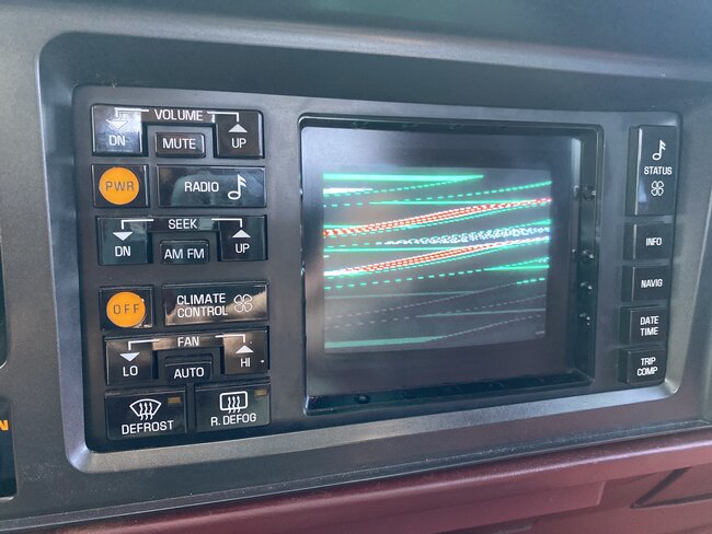
Your first photo looks like a picture tube tv that lost its horizontal hold. If that really is a picture tube, they require a really high voltage to run that tube. That can be over 20,000 volts. You'll see a fat wire with a rubber cap where it plugs into the side of the tube. Stay clear of that while the unit is running. The horizontal output circuit is what develops that high voltage, so if you can see anything on the screen, it's working, but that doesn't mean it's "in sync". Being out of sync is what makes the picture turn into those horizontal lines. That used to happen to tvs when the set was not in sync with the cameras at the tv studio, or the signal they were broadcasting. I'm not sure what they would be syncing to in a car. The tv studio, in effect, is right there in the same unit. I'm thinking out loud now. That Central Power Supply you mentioned might be the system that develops that high voltage to run the crt. If it is, follow that wire plugged into the side of the crt back to its source. That would be the high voltage transformer. In tvs, those were ripe for broken solder connections where they mounted to the circuit board. Some are held on first with two screws, then the pins are soldered to the board, but a lot of them didn't use those screws. Just the pins held the transformer in place. That's a lot of weight to ask of them, especially in a vehicle that's bouncing and vibrating. In some tv models, the right broken pin's solder connection could keep the transformer working, but the feedback circuit wasn't there to keep the screen in sync with the pulses in the broadcast signal. That would give you the horizontal lines like you have.
To say that a less-complicated way, check for more bad solder connections around that transformer. There will also be a much smaller "horizontal driver" transformer nearby. They're commonly less than an inch square and will usually have only four terminals. The high voltage will be lost if any one of those pins has a bad connection, but that gives you an idea of the area on the board to look over closer.
You can also try pressing lightly on the circuit board with a non-metal tool while the unit is running. If doing so makes things change, you know there's a hairline break or a bad connection. The problem then is to find it.
Let us know if any of those things pan out. Meanwhile, I'll keep trying to remember other hints or clues that might help.
Jul 3, 2023 at 4:50 PM