Hi,
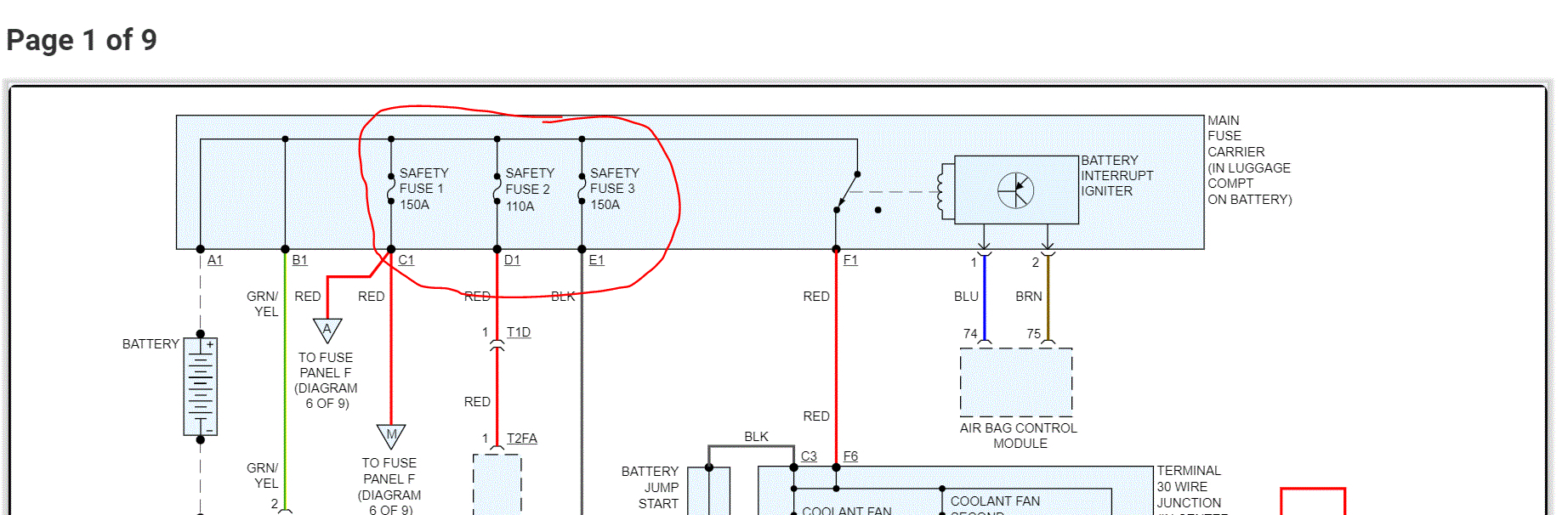
Let me know what you find with the additional fuses. As far as the HUD, there was technical service bulletin a few years back, but it dealt with flickering or dimming. You indicates there is no HUD or instrument panel, so I don't feel that is going to help.
That leads me to the CAN system. I have a specific test for the instrument panel related to the CAN bus system. Have you had the scan done I mentioned in the above post? Take a look through this and let me know if it is something you feel comfortable doing.
______________________________
CAN-Bus Terminal Resistance Instrument Cluster to Data Diagnostic Connector, Checking
Vehicle Power-train Management Computers and Control Systems Testing and Inspection Component Tests and General Diagnostics CAN-Bus Terminal Resistance Instrument Cluster to Data Diagnostic Connector, Checking
CAN-BUS TERMINAL RESISTANCE INSTRUMENT CLUSTER TO DATA DIAGNOSTIC CONNECTOR, CHECKING
CAN-Bus Terminal Resistance Instrument Cluster to Data Diagnostic Connector, Checking
The Engine Control Module (J623) communicates with all data-bus capable control modules via a CAN databus.
These databus capable control modules are connected via two data bus wires which are twisted together (CAN_High and CAN_Low), and exchange information (messages). Missing information on the databus is recognized as a malfunction and stored.
Trouble-free operation of the CAN-bus requires that it have a terminal resistance. The central terminal resistor is located in the Engine Control Module (J623).
Special tools, testers and auxiliary items required
Multi-meter.
Wiring diagram.
Test requirement
A CAN-Bus malfunction was recognized.
The Engine Control Module (J623) fuses OK.
Battery voltage at least 12.5 V.
Ignition switched OFF.
Test Procedure
- Perform a preliminary check to verify the customers complaint. Refer to => [ Preliminary Check ] See: Computers and Control Systems > Scan Tool Testing and Procedures > Preliminary Check
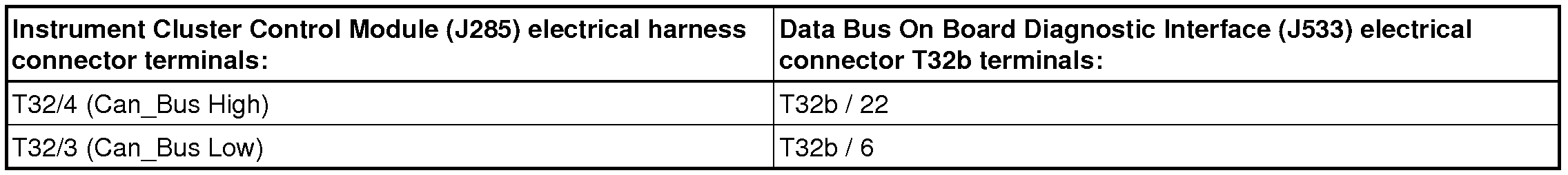
- Disconnect the Instrument Cluster Control Module (J285) electrical harness connector T32 from the Instrument Cluster Control Module.
The Engine Control Module (J623) must remain connected for the following step.
- Disconnect the Data Bus On Board Diagnostic Interface (J533) electrical harness connector T32b from the diagnostic interface.
- Using a Multi-meter , check continuity between J285 and J533.
Specified value: max. 1.5ohms (at approx. 20° C)
See pic 1
If the specified value was Not obtained:
- Check the wiring connection for an open circuit, short circuit to Battery voltage or Ground (GND).
- Check the wiring connection for damage, corrosion, lose or broken terminals.
- If necessary, repair the faulty wiring connection.
If the specified value was obtained:
- Replace the Engine Control Module (J623). Refer to Repair Manual.
Final procedures
After the repair work, the following work steps must be performed in the following sequence:
1. Check the DTC memory. Refer to => [ Diagnostic Mode 03 - Read DTC Memory ] See: Computers and Control Systems > Scan Tool Testing and Procedures > Diagnostic Mode 03 - Read DTC Memory.
2. If necessary, erase the DTC memory. Refer to => [ Diagnostic Mode 04 - Erase DTC Memory ] See: Computers and Control Systems > Scan Tool Testing and Procedures > Diagnostic Mode 04 - Erase DTC Memory.
3. If the DTC memory was erased, generate readiness code. Refer to => [ Readiness Code ] See: Computers and Control Systems > Monitors, Trips, Drive Cycles and Readiness Codes > Readiness Code.
_____________________________________________
Also, the TSB I mentioned was a programming related issue that needed updated.
Let me know.
Joe
Jul 28, 2020 at 6:45 PM