CIRCUIT/SYSTEM DESCRIPTION
The camshaft position (CMP) actuator is attached to the camshaft and is hydraulically operated in order to change the angle of the camshaft relative to crankshaft position (CKP). The CMP actuator solenoid is controlled by the control module. The control module sends a pulse width modulated 12-volt signal to a CMP actuator solenoid. The solenoid controls the amount of engine oil flow to the CMP actuator by extending a pintle within the solenoid. The pintle acts against a spool valve in the CMP actuator mechanism which is attached to the front of the camshaft. As the spool valve is moved, oil is directed to the CMP actuator, which rotates the camshaft. The CMP actuator can change the cam angle a maximum of 25 degrees.
CONDITIONS FOR RUNNING THE DTC
P0010
The ignition is in Crank or Run.
The system voltage is between 9-11 volts.
P0011
DTC P0010, P0016, P0335, P0336, P0340, or P0341 are not set.
The system voltage is more than 11 volts.
The engine is running.
The control module has enabled the CMP actuator.
DTC P0011 runs continuously when the above conditions are met.
CONDITIONS FOR SETTING THE DTC
P0010
The engine control module (ECM) detects that the state of the driver and the state of the circuit do not match. The ECM will detect an open, short to ground, or a short to voltage on the high control circuit or an open on the low reference circuit for more than 6.25 seconds.
P0011
The difference between the desired CMP and the actual CMP angle is more than 8 degrees for more than 8 seconds while the CMP actuator is being commanded. OR
The difference between the desired CMP and the actual CMP angle is more than 7.5 degrees when the CMP actuator is steady for more than 2 seconds.
ACTION TAKEN WHEN THE DTC SETS
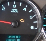
The control module illuminates the malfunction indicator lamp (MIL) when the diagnostic runs and fails.
The control module records the operating conditions at the time the diagnostic fails. The control module stores this information in the Freeze Frame and/or the Failure Records.
The control module commands the TAC system to operate in the Reduced Engine Power mode.
A message center or an indicator displays Reduced Engine Power.
Under certain conditions the control module commands the engine OFF.
CONDITIONS FOR CLEARING THE MIL/DTC
The control module turns OFF the malfunction indicator lamp (MIL) after 3 consecutive ignition cycles that the diagnostic runs and does not fail.
A current DTC, Last Test Failed, clears when the diagnostic runs and passes.
A history DTC clears after 40 consecutive warm-up cycles, if no failures are reported by this or any other emission related diagnostic.
Clear the MIL and the DTC with a scan tool.
CIRCUIT/SYSTEM VERIFICATION
Ensure the vehicle has the proper oil viscosity.
Observe the engine oil level. The engine oil level should be within operating range.
Allow the engine to reach operating temperature.
Set the parking brake and place the vehicle in park for automatic, or neutral for data.
Command the CMP actuator to 25 percent. The Desired CMP parameter should match the CMP Angle parameter.
Observe the CMP variance parameter. The CMP Variance indicates the difference in degrees between the CMP Angle and the Desired CMP. The CMP Variance will rise for 1-2 seconds until the CMP Angle parameter matches the Desired CMP parameter. The CMP Variance should again return to 0 degrees.
CIRCUIT/SYSTEM TESTING
Ignition ON, measure for battery voltage between the CMP actuator solenoid high control and ground.
If less than battery voltage, test the CMP actuator high control circuit for an open, short to ground, or a faulty ECM.
Connect a test lamp between the CMP actuator solenoid high control and ground. The test lamp should not illuminate.
If the test lamp illuminates, test the CMP actuator high control circuit for a short to voltage or a faulty ECM.
Command the CMP actuator solenoid from 0-25 percent. The test lamp should turn ON and OFF.
If test lamp does not turn ON and OFF, test the CMP actuator high control circuit for high resistance or for a faulty ECM.
Connect a test lamp between the low reference circuit of the CMP actuator solenoid and battery voltage. The test lamp should illuminate.
If the test lamp does not illuminate, test the low reference circuit for an open, high resistance, or a faulty ECM.
Determine that the vehicle has the correct engine oil. Refer to Service and Appearance Care in the Owner's data.
If the engine oil is old, burnt, contains additives, or is not the correct viscosity, change the oil and filter.
Test the engine oil pressure for correct pressure. Refer to Oil Pressure Diagnosis and Testing. See: Engine, Cooling and Exhaust Engine Testing and Inspection Component Tests and General Diagnostics
If the oil pressure is low, correct the low pressure first.
Inspect the CMP actuator for the following conditions:
Stuck
Loose
CMP actuator return spring broken
Torn screens
Debris on the screens
Debris clogging the oil ports
Missing screens
Oil seepage at the solenoid connector pins
Inspect for the following conditions:
Excessive timing chain play
Proper installation of the CMP actuator assembly
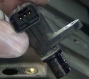
COMPONENT TESTING
Measure the resistance of the CMP actuator solenoid. Resistance should be between 4.8-5.2 ohms.
Point the CMP actuator towards a shop towel. Connect a jumper wire between the CMP actuator low reference circuit at the solenoid and ground. Connect a fused jumper wire to the CMP actuator high control circuit at the solenoid. Momentarily touch the fused jumper to battery voltage. The CMP actuator solenoid pintle should immediately extend.
REPAIR INSTRUCTIONS
IMPORTANT: Always perform the Diagnostic Repair Verification after completing the diagnostic procedure.
Control Module References for ECM replacement, setup and programming
Camshaft Position Actuator Magnet Replacement
Camshaft Position Actuator See: Verification Tests
Sunday, May 5th, 2013 AT 11:43 AM