Hi,
As far as the connector, heat can cause them to look burnt. Is it possible for you to upload a picture of it so I can see it?
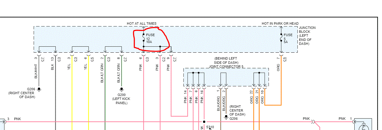
As far as the dome lights, have you checked the fuse? It is on the left side end of the dash. I attached a pic of the fuse responsible for the dome light. See pic 1
As far as the mirrors, did you install an OEM type mirror and wiring? If so, here are directions for trouble shooting. The remaining pics correlate with these directions.
________________________________________
1999 Dodge or Ram Truck RAM 1500 Truck 4WD V8-5.9L VIN Z LDC
Power Mirror System
Vehicle Body and Frame Mirrors Testing and Inspection Component Tests and General Diagnostics Power Mirror System
POWER MIRROR SYSTEM
1. Check the fuses in the Power Distribution Center (PDC) and the junction block. If OK, go to Step 2. If not OK, repair the shorted circuit or component as required and replace the faulty fuse(s).
2. Check for battery voltage at the fuse in the junction block. If OK, go to Step 3. If not OK, repair the open circuit to the PDC as required.
3. Disconnect and isolate the battery negative cable. Remove the driver side door trim panel and unplug the wire harness connector from the power mirror switch. Connect the battery negative cable. Check for battery voltage at the fused B(+) circuit cavity in the door wire harness half of the power mirror switch wire harness connector. If OK, go to Step 4. If not OK, repair the open circuit to the junction block as required.
4. Disconnect and isolate the battery negative cable. Check for continuity between the ground circuit cavity in the door wire harness half of the power mirror switch wire harness connector and a good ground. There should be continuity. If OK, go to Step 5. If not OK, repair the circuit to ground as required.
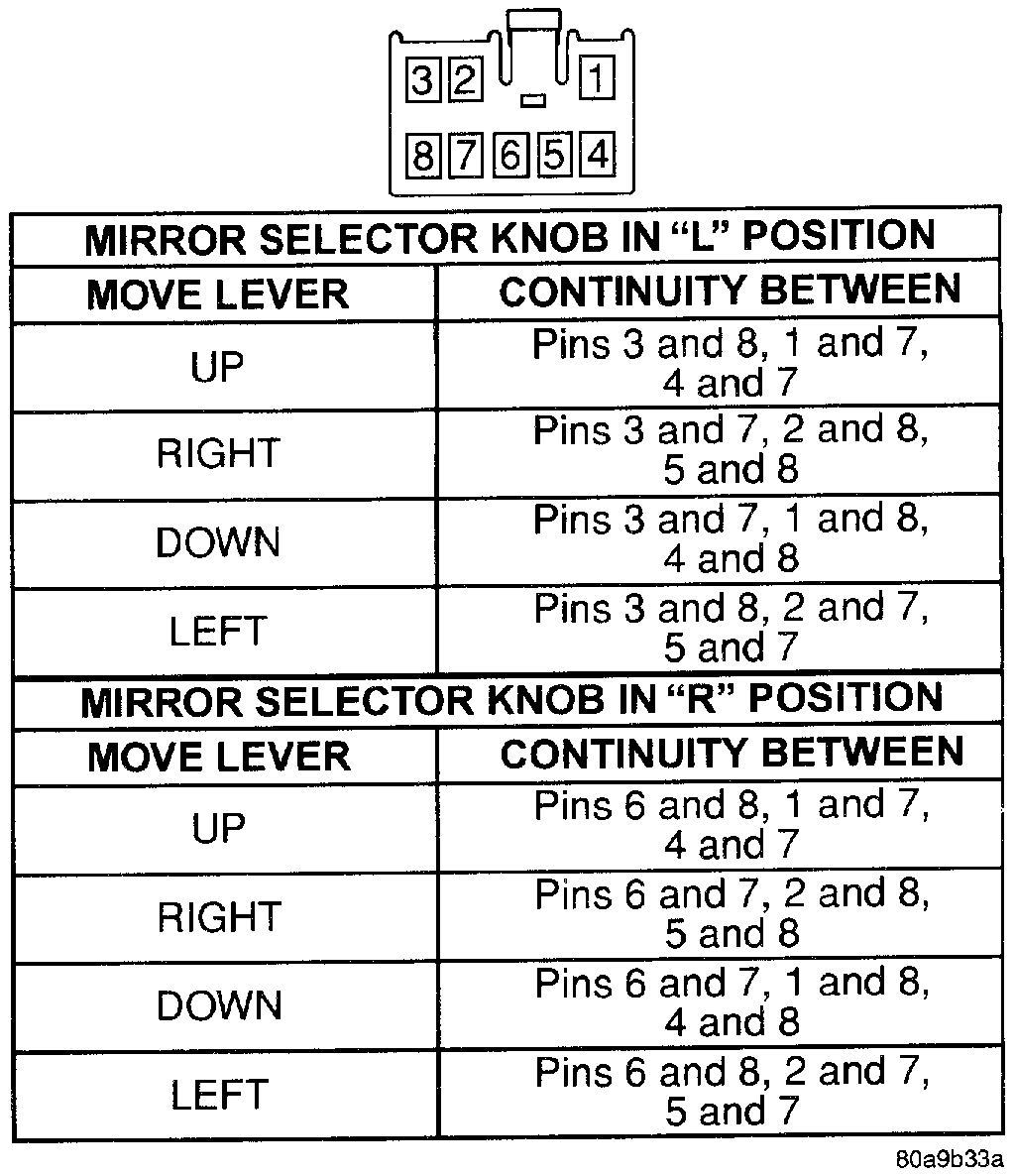
Power Mirror Switch Continuity
pic 2
5. Check the power mirror switch continuity. If OK, go to Step 6. If not OK, replace the faulty switch.
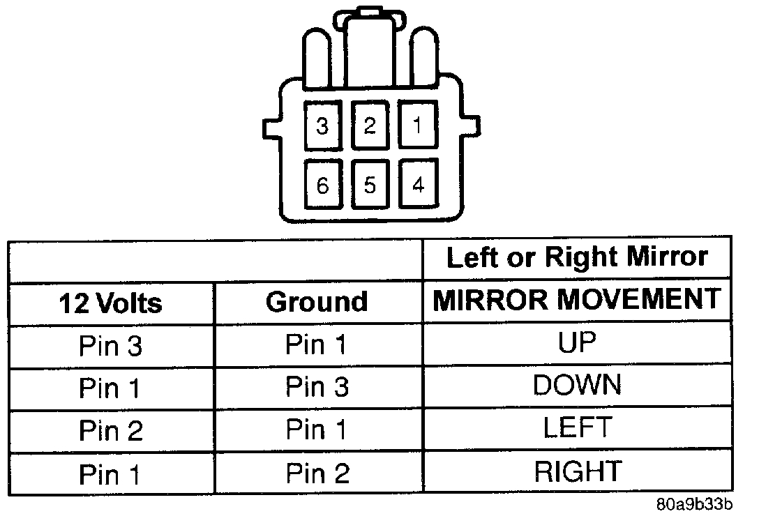
Power Mirror Test
pic 3
6. Unplug the wire harness connector at the inoperative power mirror. Use two jumper wires, one connected to a 12 volt battery feed, and the other connected to a good body ground. See the Power Mirror Test chart for the correct jumper wire connections to the power mirror half of the power mirror wire harness connector. If the power mirror(s) do not respond as indicated in the chart, replace the faulty power mirror assembly. If the power mirror(s) do respond as indicated in the chart, repair the circuits between the power mirror and the power mirror switch for a short or open as required.
_____________________
Let me know.
Joe
Images (Click to enlarge)
Feb 28, 2020 at 9:43 PM