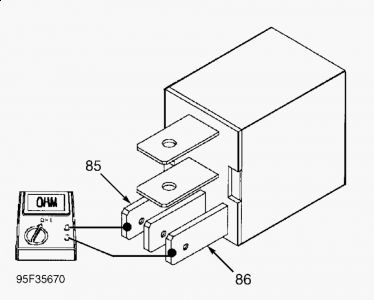
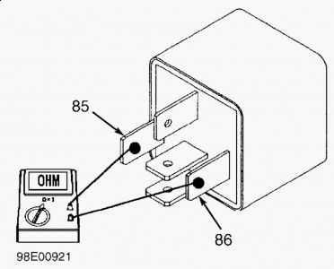
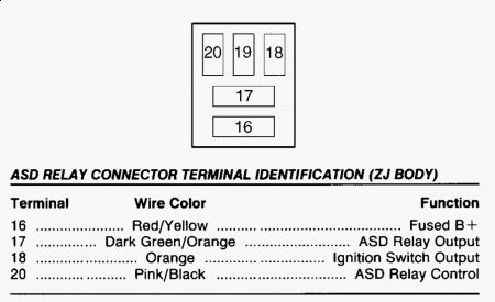
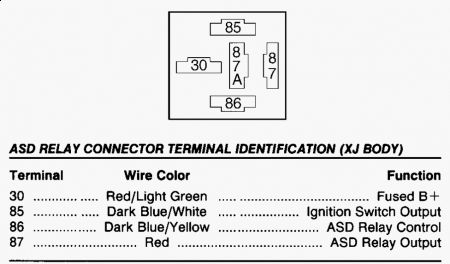
TEST TC-10A: AUTO SHUTDOWN RELAY CONTROL CIRCUIT NOTE: For connector terminal identification, see CONNECTOR IDENTIFICATION. For component location and wiring diagram, see WIRING DIAGRAMS article. Using scan tool, actuate Auto Shutdown (ASD) relay. Listen for clicking sound at ASD relay. If no clicking sound is heard at ASD relay, go to step 6) . If clicking sound is heard at ASD relay, go to next step. 1. Condition required to set DTC is not present at this time. AUTO SHUTDOWN RELAY CONTROL CIRCUIT DTC sets if Powertrain Control Module (PCM) detects an open or shorted condition in ASD relay control circuit. Possible causes are: open or shorted relay coil, open fused ignition output circuit, open or shorted ASD relay control circuit, defective PCM, defective connector terminals or connector wires. Go to next step. 2. Inspect all related wiring and connectors. Repair wiring and connectors as necessary and perform TEST VER-2A: ROAD TEST VERIFICATION . If wiring and connectors are okay, start engine. If vehicle is equipped with a diesel engine, go to step 5) . On all other vehicles, go to next step. 3. Wiggle wiring harness from ASD relay to PCM. If engine stalls while wiggling wiring harness, repair wiring as necessary and perform TEST VER-2A: ROAD TEST VERIFICATION . If engine does not stall, see INACTIVE DTC CONDITION . Test is complete. Perform TEST VER-2A: ROAD TEST VERIFICATION . 4. Disconnect intake air temperature heater relay control connector. Turn headlights on and wiggle wiring harness from ASD relay to PCM. If headlights flicker while wiggling wiring harness, repair wiring as necessary and perform TEST VER-2A: ROAD TEST VERIFICATION . If headlights do not flicker, see INACTIVE DTC CONDITION . Test is complete. Perform TEST VER-2A: ROAD TEST VERIFICATION . 5. Remove ASD relay from power distribution center. Inspect ASD relay connector and terminals for damage. Repair connector and terminals as necessary and perform TEST VER-2A: ROAD TEST VERIFICATION . If connectors and terminals are okay, go to next step. 6. Using scan tool in voltmeter mode, check voltage on ASD relay connector, fused ignition switch output circuit (Red/Light Green wire on TJ body; Dark Blue/White wire on XJ body; Orange wire on ZJ body; Light Green/Black wire on all other bodies). If voltage is 10 volts or less, repair open in fused ignition switch output circuit and perform TEST VER-2A: ROAD TEST VERIFICATION . If voltage is more than 10 volts, go to next step. 7. Using an external ohmmeter, check resistance between ASD relay terminals No. 85 and 86. See Fig. 76 or Fig. 77 . If resistance is 100 ohms or more, replace ASD relay and perform TEST VER-2A: ROAD TEST VERIFICATION . If resistance is less than 100 ohms, go to next step. 8. Ensure ignition is off. Disconnect Powertrain Control Module (PCM) Gray connector. Inspect connector and terminals for damage. Repair connector and terminals as necessary and perform TEST VER-2A: ROAD TEST VERIFICATION . If connector and terminals are okay, go to next step. 9. Check resistance between ground and PCM Gray connector, ASD relay control circuit (Pink/Black wire on ZJ body; Dark Blue/Yellow wire on all other bodies). If resistance is less than 5 ohms, repair short to ground in ASD relay control circuit and perform TEST VER-2A: ROAD TEST VERIFICATION . If resistance is 5 ohms or more, go to next step. 10. Check resistance of ASD relay control circuit (Pink/Black wire on ZJ body; Dark Blue/Yellow wire on all other bodies) between ASD relay connector and PCM Gray connector. If resistance is 5 ohms or more, repair open ASD relay control circuit and perform TEST VER-2A: ROAD TEST VERIFICATION . If resistance is less than 5 ohms, replace PCM and perform TEST VER-2A: ROAD TEST VERIFICATION . 11.
This is the P1388 code, and if ASD circuit malfunctions, truck wont run...
Your relay should be one of these...
Saturday, January 23rd, 2010 AT 10:56 AM


