Hello -
DTC P0131: 1/1 O2 SENSOR SHORTED TO GROUND
NOTE: For connector terminal ID, see CONNECTOR IDENTIFICATION . For wiring diagram, see WIRING DIAGRAMS article.
NOTE: The 1/1 oxygen sensor may also be referred to as upstream oxygen sensor. 1/1 oxygen sensor is monitored at a cold start, engine coolant temperature is less than 98 °F (37 °C) and ambient/battery temperature sensor reading is within 27 °F (-2.8 °C) of engine coolant temperature and engine coolant temperature is more than 170 °F (77 °C) the last time ignition was on. DTC may be stored in Powertrain Control Module (PCM) if 1/1 oxygen sensor signal voltage is less than .156 volt for 28 seconds after engine is started. Possible causes are: defective 1/1 oxygen sensor, defective Auto Shutdown (ASD) relay, defective oxygen sensor upstream heater relay, defective PCM, or defective connectors or wiring
1. Turn ignition on with engine off. Using scan tool, check for DTCs. If DTC SPECIFIC GOOD TRIP counter is displayed and equal to zero, go to next step. If DTC SPECIFIC GOOD TRIP counter is not displayed and equal to zero, go to step 6 .
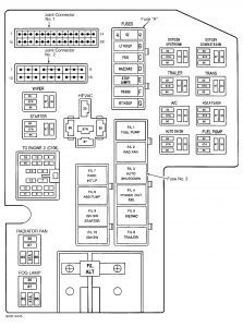
2. Ensure ignition is on with engine off. Using scan tool, actuate oxygen sensor heater test and then use scan tool to monitor 1/1 oxygen sensor voltage for 2-3 minutes. Oxygen sensor heater test may also be referred to as O2 heater test. 1/1 oxygen sensor voltage should be more than 3.5 volts at start of oxygen sensor heater test and then become less than 1.5 volts within 2-3 minutes. If 1/1 oxygen sensor voltage is not less than 1.5 volts at start of oxygen sensor heater test, stop oxygen sensor heater test. Go to next step. If 1/1 oxygen sensor voltage is less than 1.5 volts at start of oxygen sensor heater test, repair short to voltage on 1/1 oxygen sensor heater circuit. On 4.7L Calif. emission vehicles, 1/1 oxygen sensor heater circuit is the Dark Green/Red wire between oxygen sensor upstream heater relay and 1/1 oxygen sensor. Voltage may also be caused by oxygen sensor upstream heater relay which is stuck closed and provides voltage to oxygen sensor heater all the time. Oxygen sensor upstream heater relay is located in power distribution center at driver's side front corner of engine compartment, near battery. See Fig. 3 . The 1/1 oxygen sensor is located on driver's side exhaust pipe, just below exhaust manifold and in front of small catalytic converter. On 4.7L except Calif. emission vehicles, 2.5L, 3.9L and 5.9L, 1/1 oxygen sensor heater circuit is the Orange/Dark Green wire between fuse "A" (15-amp) and 1/1 oxygen sensor. Fuse "A" may also be referred to as O2 SSR fuse. Voltage may also be caused by ASD relay which is stuck closed and provides voltage to oxygen sensor heater all the time. Fuse "A" and ASD relay are located in power distribution center at driver's side front corner of engine compartment, near battery. See Fig. 3 . The 1/1 oxygen sensor is located on exhaust pipe in front of catalytic converter. On all models, once short to voltage is repaired, perform TEST VER-5 .
3. Ensure ignition is on with engine off. Using scan tool, monitor 1/1 oxygen sensor voltage while disconnecting 1/1 oxygen sensor connector. On 4.7L Calif. emission vehicles, 1/1 oxygen sensor is located on driver's side exhaust pipe, just below exhaust manifold and in front of small catalytic converter. On 4.7L except Calif. emission vehicles, 2.5L, 3.9L and 5.9L, 1/1 oxygen sensor is located on exhaust pipe in front of catalytic converter. On all models, if 1/1 oxygen sensor voltage does not change from less than one volt to more than 4.5 volts, go to next step. If 1/1 oxygen sensor voltage changes from less than one volt to more than 4.5 volts, replace 1/1 oxygen sensor. Perform TEST VER-5 .
4. Turn ignition off. Disconnect PCM connectors. PCM is located at passenger's side front corner of engine compartment on inner fender panel. Ensure 1/1 oxygen sensor connector is still disconnected. Using ohmmeter, check resistance between terminals No. 3 (Black/Light Blue wire) and No. 4 (Light Green/Red wire on 4.7L or Tan/White wire on 2.5L, 3.9L and 5.9L) on 1/1 oxygen sensor connector. If resistance is 5 ohms or more, go to next step. If resistance is less than 5 ohms, repair Black/Light Blue and Light Green/Red wire (4.7L) or Tan/White wire (2.5L, 3.9L and 5.9L) between 1/1 oxygen sensor and PCM as they are shorted together. Perform TEST VER-5 .
5. Ensure PCM connectors and 1/1 oxygen sensor connector are still disconnected. Using ohmmeter, check resistance between ground and terminal No. 4 (Light Green/Red wire on 4.7L or Tan/White wire on 2.5L, 3.9L and 5.9L) on 1/1 oxygen sensor connector. If resistance is 5 ohms or more, replace PCM. Perform TEST VER-5 . If resistance is less than 5 ohms, repair short to ground on Light Green/Red wire (4.7L) or Tan/White wire (2.5L, 3.9L and 5.9L) between 1/1 oxygen sensor and PCM. Perform TEST VER-5 .
6. Start engine and allow engine to idle. Wiggle wiring harness and connectors between PCM and 1/1 oxygen sensor while noting DTC SPECIFIC GOOD TRIP counter. PCM is located at passenger's side front corner of engine compartment on inner fender panel. On 4.7L Calif. emission vehicles, 1/1 oxygen sensor is located on driver's side exhaust pipe, just below exhaust manifold and in front of small catalytic converter. On 4.7L except Calif. emission vehicles, 2.5L, 3.9L and 5.9L, 1/1 oxygen sensor is located on exhaust pipe in front of catalytic converter. On all models, if DTC SPECIFIC GOOD TRIP counter does not change to zero while wiggling wiring harness and connectors, go to next step. If DTC SPECIFIC GOOD TRIP counter changes to zero while wiggling wiring harness and connectors, repair wiring or connectors between PCM and 1/1 oxygen sensor as necessary. Perform TEST VER-5 .
7. Shut engine off. Ensure ignition is off. Disconnect 1/1 oxygen sensor connector and PCM connectors. Inspect 1/1 oxygen sensor connector and PCM connectors for corroded, pushed out, miswired or damaged terminals. Inspect wiring harness between PCM and 1/1 oxygen sensor for any possible intermittent problems. Also, check for related Technical Service Bulletins (TSBs). If terminals are not corroded, pushed out or damaged and wiring harness is okay, test is complete. If terminals are corroded, pushed out or damaged or wiring harness is damaged, repair as necessary. Perform TEST VER-5 .
If you can not see Fig 3 below after saving to your PC let me know and I will try to blow it up more if you need it.
DTC P0141: 1/2 O2 SENSOR HEATER FAILURE
NOTE: For connector terminal ID, see CONNECTOR IDENTIFICATION . For wiring diagram, see WIRING DIAGRAMS article.
NOTE: The 1/2 oxygen sensor may also be referred to as downstream oxygen sensor. 1/2 oxygen sensor heater is monitored when battery voltage is more than 9 volts, at a cold start, engine coolant temperature is less than 147 °F (64 °C), battery temperature is within 27 degrees of engine temperature and engine has been idling for at least 12 seconds. DTC may be stored in Powertrain Control Module (PCM) if 1/2 oxygen sensor voltage is more than 3 volts for 60-240 seconds. Possible causes are: defective 1/2 oxygen sensor or heater, defective Auto Shutdown (ASD) relay circuit, defective oxygen sensor downstream heater relay, or defective connectors or wiring.
1. Turn ignition on with engine off. Using scan tool, check for DTCs. If DTC SPECIFIC GOOD TRIP counter is displayed and equal to zero, go to next step. If DTC SPECIFIC GOOD TRIP counter is not displayed and equal to zero, go to step 12 .
2. On 4.7L Calif. emission vehicles, go to next step. On 4.7L except Calif. emission vehicles, 2.5L, 3.9L and 5.9L, go to step 9 .
3. Turn ignition off. Check for open or defective fuse "A" which may also be referred to as O2 SSR fuse. Fuse "A" is located in power distribution center at driver's side front corner of engine compartment, near battery. See Fig. 3 . If fuse "A" is open or defective, go to next step. If fuse "A" is okay, go to step 5 .
4. Ensure ignition is off and fuse "A" is removed from power distribution center. Remove oxygen sensor downstream heater relay from power distribution center. See Fig. 3 . Oxygen sensor downstream heater relay may be referred to as oxygen downstream relay. Note cavities in power distribution center for oxygen sensor downstream heater relay. See Fig. 3 . Using ohmmeter, check resistance between ground and cavity No. 30 (Orange/Dark Green wire) in power distribution center for oxygen sensor downstream heater relay. If resistance is 5 ohms or more, replace fuse "A" and reinstall oxygen sensor downstream heater relay. Perform TEST VER-5 . If resistance is less than 5 ohms, repair short to ground on Orange/Dark Green wire between cavity No. 30 in power distribution center for oxygen sensor downstream heater relay, joint connector No. 2 and fuse "A". Joint connector No. 2 is located in power distribution center. See Fig. 3 . Replace fuse "A" and reinstall oxygen sensor downstream heater relay. Perform TEST VER-5 .
5. Ensure ignition is off and fuse "A" is removed from power distribution center. Remove oxygen sensor downstream heater relay from power distribution center. See Fig. 3 . Oxygen sensor downstream heater relay may be referred to as oxygen downstream relay. Note cavities in power distribution center for oxygen sensor downstream heater relay and cavity A2 for fuse "A". See Fig. 3 . Using ohmmeter, check resistance between cavity No. 30 (Orange/Dark Green wire) in power distribution center for oxygen sensor downstream heater relay and cavity A2 (Orange/Dark Green wire) in power distribution center for fuse "A". If resistance is less than 5 ohms, reinstall fuse "A" and oxygen sensor downstream heater relay. Go to next step. If resistance is 5 ohms or more, repair open on Orange/Dark Green wire between cavity No. 30 in power distribution center for oxygen sensor downstream heater relay, joint connector No. 2 and fuse "A". Joint connector No. 2 is located in power distribution center. See Fig. 3 . Reinstall oxygen sensor downstream heater relay. Perform TEST VER-5 .
6. Ensure ignition is off. Disconnect 1/2 oxygen sensor connector. The 1/2 oxygen sensor is located on driver's side exhaust pipe, just below small catalytic converter. Using ohmmeter, check resistance between ground and terminal No. 2 (Black wire) on 1/2 oxygen sensor connector. If resistance is less than 5 ohms, go to next step. If resistance is 5 ohms or more, repair open on Black wire between 1/2 oxygen sensor and ground connection. Ground connection is located near front of passenger's side of engine, below A/C compressor. Perform TEST VER-5 .
7. Ensure 1/2 oxygen sensor connector is still disconnected. Turn ignition on with engine off. Using scan tool, actuate oxygen sensor downstream heater relay. Using voltmeter, check voltage at terminal No. 1 (Dark Green/Pink wire) on 1/2 oxygen sensor connector. If voltage is more than 10 volts, stop actuation of oxygen sensor downstream heater relay. Go to next step. If voltage is 10 volts or less, repair open on Dark Green/Pink wire between 1/2 oxygen sensor and cavity No. 87 in power distribution center for oxygen sensor downstream heater relay. Perform TEST VER-5 .
8. Turn ignition off. Ensure 1/2 oxygen sensor connector is still disconnected. Using ohmmeter, check resistance of 1/2 oxygen sensor heater between terminals No. 1 and 2 on oxygen sensor side of 1/2 oxygen sensor connector. These terminals correspond with Dark Green/Pink wire and Black wire on wiring harness side of 1/2 oxygen sensor connector. If resistance is 4-7 ohms, replace oxygen sensor downstream heater relay as it is assumed that an intermittent problem exists with the relay. Perform TEST VER-5 . If resistance is not 4-7 ohms, replace 1/2 oxygen sensor. Perform TEST VER-5 .
9. Turn ignition off. Disconnect 1/2 oxygen sensor connector. The 1/2 oxygen sensor is located on exhaust pipe behind catalytic converter. Turn ignition on with engine off. Using scan tool, actuate oxygen sensor heater test. Oxygen sensor heater test may also be referred to as O2 heater test. Using voltmeter, check voltage at terminal No. 1 (Orange/Dark Green wire) on 1/2 oxygen sensor connector. If voltage is more than 11 volts, go to next step. If voltage is 11 volts or less, repair open on Orange/Dark Green wire between fuse "A" (15-amp) and 1/2 oxygen sensor. It may be necessary to check for open on Dark Green/Orange wire between Auto Shutdown (ASD) relay, joint connector No. 2 and fuse "A". Fuse "A" which may also be referred to as O2 SSR fuse, ASD relay and joint connector No. 2 are located in power distribution center. See Fig. 3 . Power distribution center is located at driver's side front corner of engine compartment, near battery. Perform TEST VER-5 .
10. Stop actuation of oxygen sensor heater test. Turn ignition off. Ensure 1/2 oxygen sensor connector is still disconnected. Using ohmmeter, check resistance between ground and terminal No. 2 (Black wire) on 1/2 oxygen sensor connector. If resistance is less than 5 ohms, go to next step. If resistance is 5 ohms or more, repair open on Black wire between 1/2 oxygen sensor and ground connection. Ground connection is located near front of passenger's side of engine, below A/C compressor. Perform TEST VER-5 .
11. Ensure 1/2 oxygen sensor connector is still disconnected. Using ohmmeter, check resistance of 1/2 oxygen sensor heater between terminals No. 1 and 2 on oxygen sensor side of 1/2 oxygen sensor connector. These terminals correspond with Orange/Dark Green wire and Black wire on wiring harness side of 1/2 oxygen sensor connector. If resistance is 4-7 ohms, test is complete. If resistance is not 4-7 ohms, replace 1/2 oxygen sensor. Perform TEST VER-5 .
12. Start engine and allow engine to idle. With engine idling, wiggle wiring harness and connectors between PCM and 1/2 oxygen sensor while noting DTC SPECIFIC GOOD TRIP counter. PCM is located at passenger's side front corner of engine compartment on inner fender panel. On 4.7L Calif. emission vehicles, 1/2 oxygen sensor is located on driver's side exhaust pipe, just below small catalytic converter. On 4.7L except Calif. emission vehicles, 2.5L, 3.9L and 5.9L, 1/2 oxygen sensor is located on exhaust pipe behind catalytic converter. On all models, if DTC SPECIFIC GOOD TRIP counter does not change to zero while wiggling wiring harness and connectors, go to next step. If DTC SPECIFIC GOOD TRIP counter changes to zero while wiggling wiring harness and connectors, repair wiring or connectors between PCM and 1/2 oxygen sensor as necessary. Perform TEST VER-5 .
13. Shut engine off. Ensure ignition is off. Disconnect 1/2 oxygen sensor connector and PCM connectors. Inspect 1/2 oxygen sensor connector and PCM connectors for corroded, pushed out, miswired or damaged terminals. Inspect wiring harness between PCM and 1/2 oxygen sensor for any possible intermittent problems. Also, check for related Technical Service Bulletins (TSBs). If terminals are not corroded, pushed out or damaged and wiring harness is okay, test is complete. If terminals are corroded, pushed out or damaged or wiring harness is damaged, repair as necessary. Perform TEST VER-5 .
Also here is that TEST VER 5 it keeps referring to.
TEST VER-3: CHARGING SYSTEM VERIFICATION
NOTE: If Powertrain Control Module (PCM) was replaced, the correct vehicle mileage and Vehicle Identification Number (VIN) must be programmed into PCM to prevent DTCs from being stored Anti-Lock Brake System (ABS) module and Supplemental Restraint System (SRS) module. To program PCM and clear DTCs from ABS and SRS modules, proceed to appropriate procedure.
Programming PCM & Clearing DTCs From ABS & SRS Modules
Connect scan tool to Data Link Connector (DLC). Using scan tool, enter correct VIN and mileage into PCM. Using scan tool manufacturer's instructions, clear DTCs from ABS and SRS modules. Proceed to final procedure.
Final Procedure
1. Inspect vehicle to ensure all components related to the repair are properly connected. Reassemble and reconnect components as necessary.
2. Using scan tool, clear DTCs from PCM. To ensure no charging system problem exists, start engine. Perform charging system output test. Increase engine speed to 2000 RPM for at least 30 seconds. Allow engine to idle. Shut engine off.
3. Using scan tool, check for DTCs. If no DTCs exist, test is complete. If repaired DTC has reset or any DTCs exist, repair is not complete. Check for related Technical Service Bulletins (TSBs) and proceed to appropriate DTC test.
Feb 24, 2009 at 4:41 PM