Blowing engine fuses

Tiny
F911MAN
  • MEMBER
  • 1999 DODGE CARAVAN
Electrical problem 6 cyl Front Wheel Drive Automatic 160000 miles

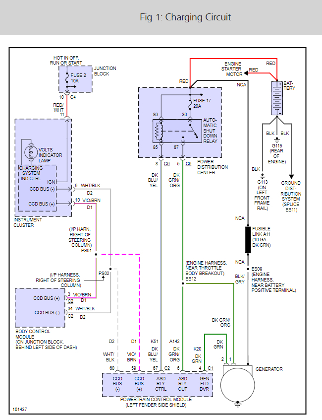
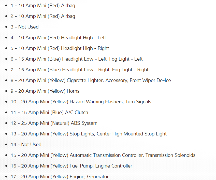
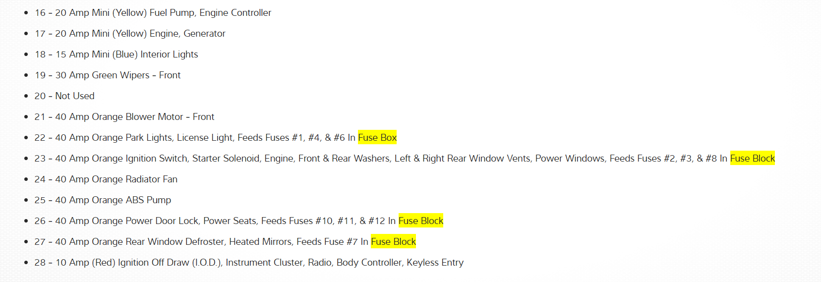
The alternator went out on my Dad's 99 Caravan. After driving it around for a 2 days he finally brought it to me to replace the alternator, after replacing the alternator and charging the battery on trickle charge for 12 hours he was good to go or so I thought. He went 4 blocks and the engine fuse blew, I replaced it and brought it back to my house, checked all the wires on the alternator and everything looks good, checked the voltage at the battery and I am only getting 13.5 with the van running, any ideas as to why it is blowing the engine fuse? It is a 20amp fuse located in the panel under the hood. I think it might also be called an ignition fuse on some consoles this one is called an engine fuse. Thank you.
Do you
have the same problem?
Yes
No
Friday, July 9th, 2010 AT 7:54 AM

11 Replies

Tiny
INTERNETMECHANIC
  • MECHANIC
  • 700 POSTS
It sounds like you have a defective alternator which you can see from this wiring diagram (below) I would remove the alternator and install an different unit AC Delco work really well.

Here is a guide to show you what you are in for when doing the job.

https://www.2carpros.com/articles/how-to-replace-an-alternator

Here is how is will be like on your car (below) And we have the fuse panel diagrams as well.

Please run some tests and get back to us.

Cheers
Was this
answer
helpful?
Yes
No
-1
Friday, July 9th, 2010 AT 7:55 PM
Tiny
F911MAN
  • MEMBER
  • 2 POSTS
Starting at the end with the 10 amp memory fuse, the first fuse is a 15 amp fuse, then a 20 amp fuse, that 20 amp fuse next to the 15 amp is the one. Another way for me to describe it is from the bottom of the picture, it would be the second fuse from the bottom on the far right of the picture, the mini fuses. Finally I changed out the alternator and you where right the problem is gone. You people are so smart! I love this site.
Was this
answer
helpful?
Yes
No
-1
Friday, July 9th, 2010 AT 8:01 PM
Tiny
INTERNETMECHANIC
  • MECHANIC
  • 700 POSTS
Nice work, we are here to help, please use 2CarPros anytime.

Cheers
Was this
answer
helpful?
Yes
No
Friday, July 9th, 2010 AT 8:41 PM
Tiny
METALMAN79
  • MEMBER
  • 1 POST
  • 1996 DODGE CARAVAN
When I try to start my 1996 dodge grand caravan, the 25 amp engine fuse in the PCM blows right away while I'm still cranking the engine. What should I check?
Was this
answer
helpful?
Yes
No
+1
Thursday, November 30th, 2017 AT 1:04 PM (Merged)
Tiny
CARADIODOC
  • MECHANIC
  • 33,699 POSTS
To prevent wasting fuses, use a pair of spade terminals plugged into the fuse socket, and a pair of jumper wires to connect them to a 12 volt light bulb. When you crank the engine, the automatic shutdown relay will turn on and the short will make the bulb get full brightness. It will also turn on for one second after turning on the ignition switch before you start cranking the engine. Now you can unplug things that are on that circuit to see which one makes the light go dim or out, indicating you removed the short from the circuit.

Depending which engine you have, disconnect the ignition coil or unplug the coil pack first. The next, and most likely suspect is wiring to one of the oxygen sensors fell down onto hot exhaust parts, melted, and shorted the internal heater wire ground. The alternator field and injectors are on that circuit too. The fuel pump should be on a different relay but powered through the ASD relay too. Unplug the fuel pump relay to isolate the pump.
Was this
answer
helpful?
Yes
No
+1
Thursday, November 30th, 2017 AT 1:04 PM (Merged)
Tiny
RAYMOND PRINCIPE
  • MEMBER
  • 1 POST
Replace airflow censor! But when trying to start vehicle it is blowing a fuse
Was this
answer
helpful?
Yes
No
-1
Thursday, November 30th, 2017 AT 1:04 PM (Merged)
Tiny
0851WALTER
  • MEMBER
  • 2 POSTS
  • 2001 DODGE CARAVAN
  • 3.3L
  • 6 CYL
  • 2WD
  • AUTOMATIC
  • 191,000 MILES
The IPM diagram shows something it terms as a spare relay. It occupies a position close to the firewall, and if you lift the IPM, you can see that it is also the location closest to the 12 volt main feed input cable.

If it were a spare in the conventional terms, it would not control anything, or be fed power. This one is. It does not show up on my factory service manual in any diagram.

Anyone know what it is there for, what it controls, and a pinout (other than the 12 volt feed).

Thanks
Was this
answer
helpful?
Yes
No
Thursday, November 30th, 2017 AT 1:04 PM (Merged)
Tiny
CARADIODOC
  • MECHANIC
  • 33,699 POSTS
Pop its cover off, reinstall it that way, then squeeze the contact to see what turns on. It could be a dealer-installed option. Another way to bypass it is to jump terminals 30 and 87 together with a stretched-out paper clip or piece of wire.
Was this
answer
helpful?
Yes
No
Thursday, November 30th, 2017 AT 1:04 PM (Merged)
Tiny
0851WALTER
  • MEMBER
  • 2 POSTS
Thanks for the tip. That was not productive though. I had a ECU fried by eighteen burnt wires under the coil pack where the transmission mount point failed. Having repaired that, I got a new computer but do not want to fry it if something else went with it the first time.

The spare relay has power to one leg, (30 as expected) 0 volts (also as expected) and two low voltage readings on the other two legs (totally unexpected).

I went way beyond what you recommended though. I completely disassembled the unit to see what feeds it provided. The thing is a bag of snakes and you cannot tell what it is feeding regardless without probing the FCM. There are not (that I could find) any references to the device in factory service manuals, and no true circuit diagrams exist of the IPM.
Was this
answer
helpful?
Yes
No
Thursday, November 30th, 2017 AT 1:04 PM (Merged)
Tiny
CARADIODOC
  • MECHANIC
  • 33,699 POSTS
Not sure what else to tell you. A relay is expected to turn on at times, and nothing should be damaged when it does. Your only other solution is to follow the wire from terminal 87 and see where it goes.

Sometimes you can get a clue by looking at the two smaller wires. On the majority of computer-controlled circuits, the relay's coil is fed with 12 volts, either constantly or when the ignition switch is on, and the computer switches the ground side to activate the relay. That means, if you take the readings with the relay plugged in, you'll have 12 volts on both wires until one gets grounded to activate it.

Most commonly, when you have an owner-installed circuit, one of the smaller relay wires is grounded, and the switching is done on the 12 volt side. The relay will operate just fine either way, but a switched 12 volt side makes more sense to most of us.

Those are just generalizations, but they might help you solve this.
Was this
answer
helpful?
Yes
No
Thursday, November 30th, 2017 AT 1:04 PM (Merged)
Tiny
KEN L
  • MASTER CERTIFIED MECHANIC
  • 42,554 POSTS
Hello,

Here is the IPMA diagram and the wiring diagrams that go with it so we can find out what the extra relay does.

Please let us know what you find. We are interested to see what it is.

Cheers, Ken
Was this
answer
helpful?
Yes
No
Saturday, December 2nd, 2017 AT 5:46 PM

Please login or register to post a reply.

Sponsored links