Welcome to 2CarPros.
Honestly, there is supposed to be arrows pointing which side should point to the axle, but nothing for left and right. Is there anything that could indicate link a mark on one of them, bearing wear or anything?
As far as the tooling, you need a torque wrench for preload, and what I have done to set back lash is use a ball joint dial indicator. I secure it on the housing and then it can be used to check play. I wish I had a better answer on the bearing caps for you.
I don't know if you need it, but I will provide the assembly directions. It includes all the specs and you may find it helpful
______________________________________
2002 Ford Truck Explorer 4WD V6-4.0L VIN E
Assembly
Vehicle Transmission and Drivetrain Differential Assembly Service and Repair Procedures Rear Drive Axle/Differential - Ford 8.8-Inch Ring Gear Disassembly and Assembly Axle Assembly
Initial assembly
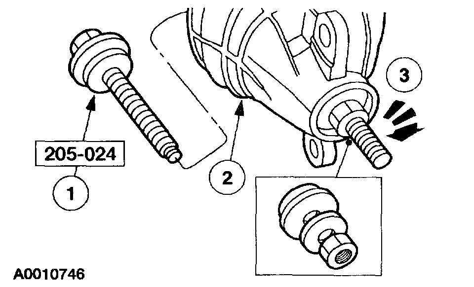
1. Coat the new differential drive pinion bearing cup(s) with lubricant.
pic 1
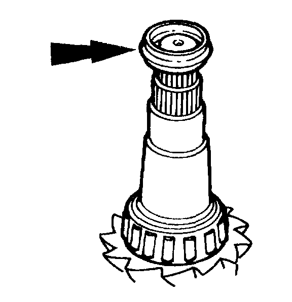
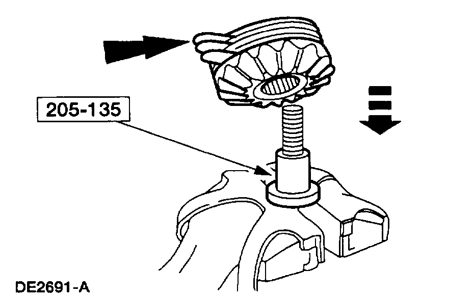
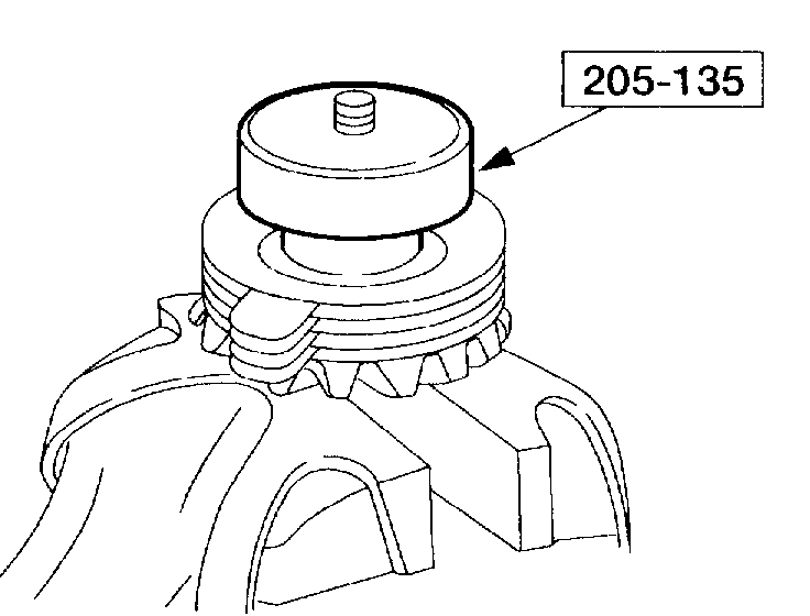
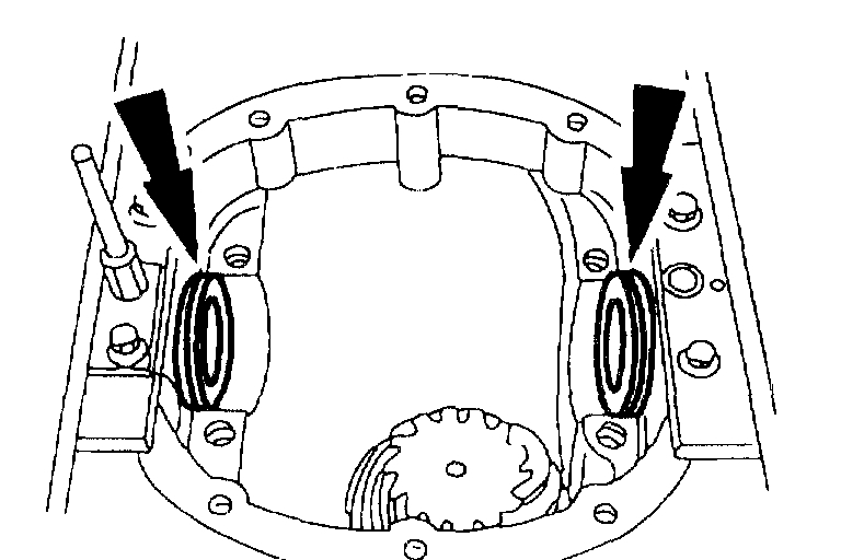
2. Using the special tool, install the differential drive pinion bearing cup(s).
1 Position the bearing cup(s) on the special tool.
2 Position the special tool and the bearing cup(s) in the differential housing.
3 Tighten the special tool to fully seat the bearing cup(s) in the bore(s).
pic 2
pic 3
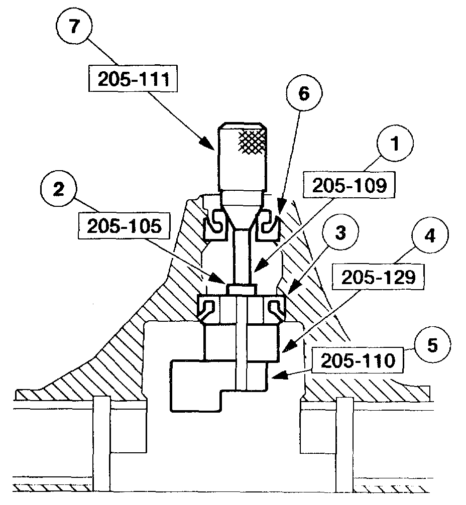
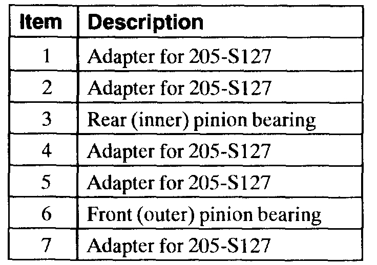
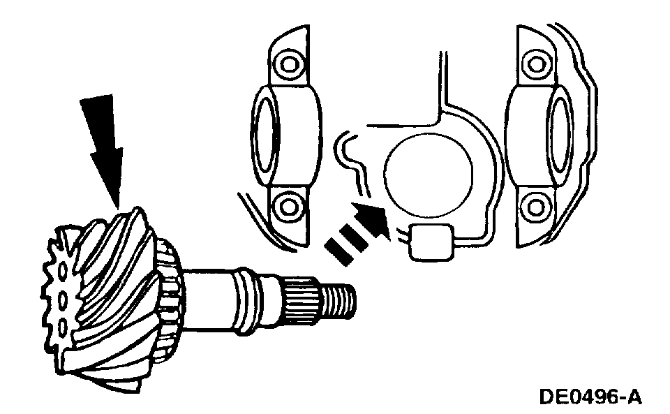
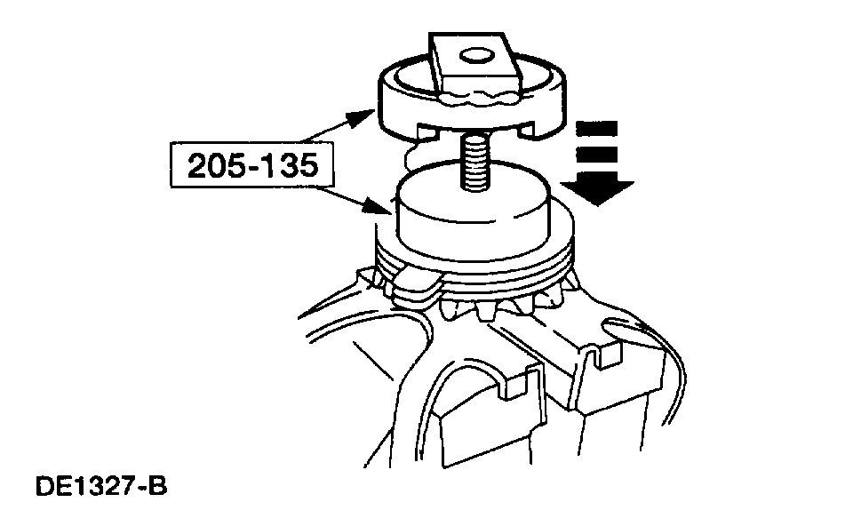
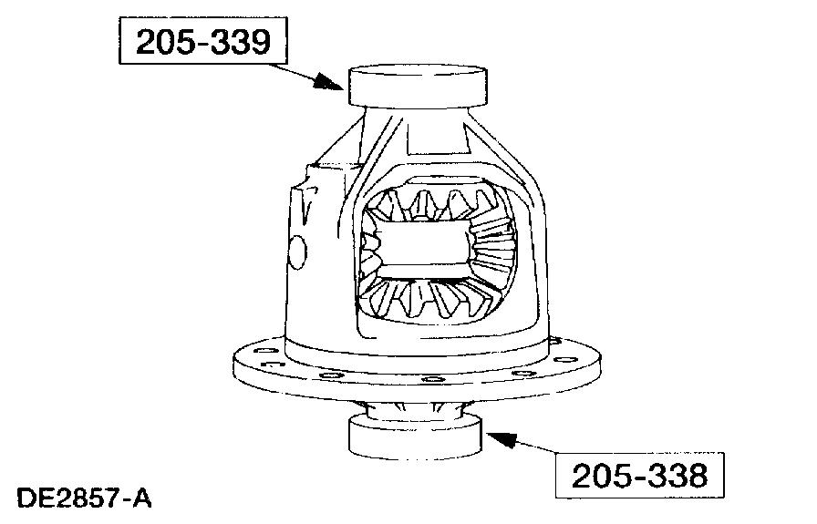
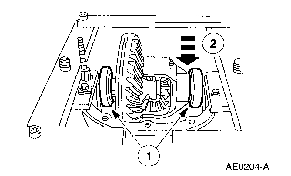
3. NOTE: Apply a light film of lubricant on the front and rear pinion bearings.
Install the pinion bearings and special tools as shown.
pic 4
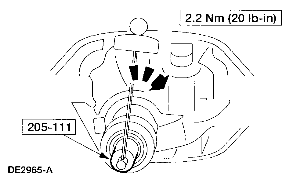
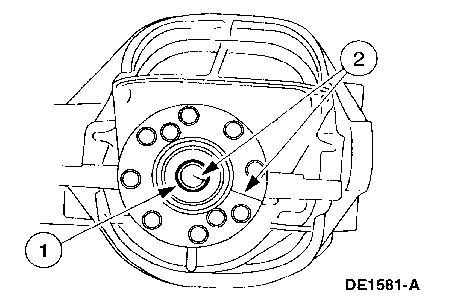
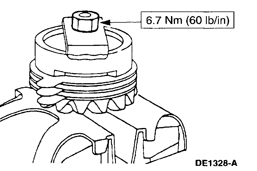
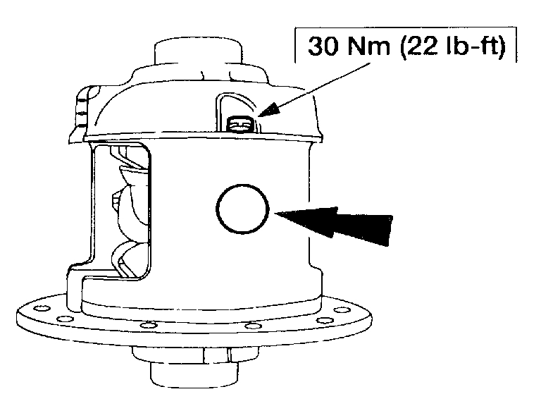
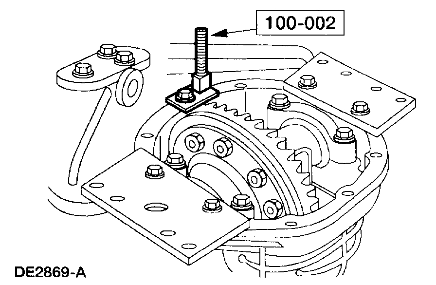
4. NOTE: This step duplicates pinion bearing preload.
Thread the special tool onto the Screw and tighten to the specification shown.
pic 5
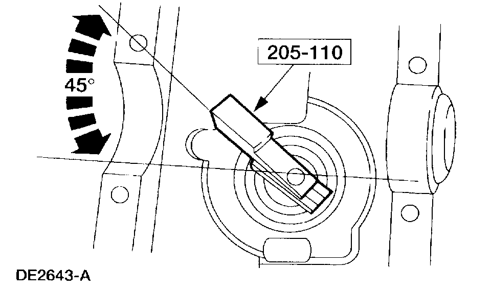
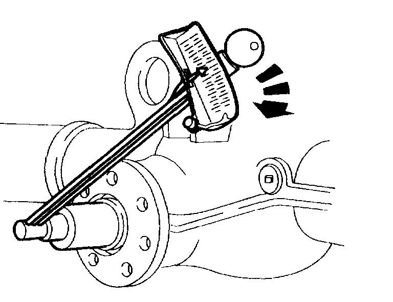
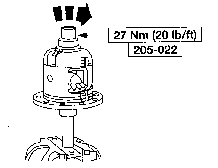
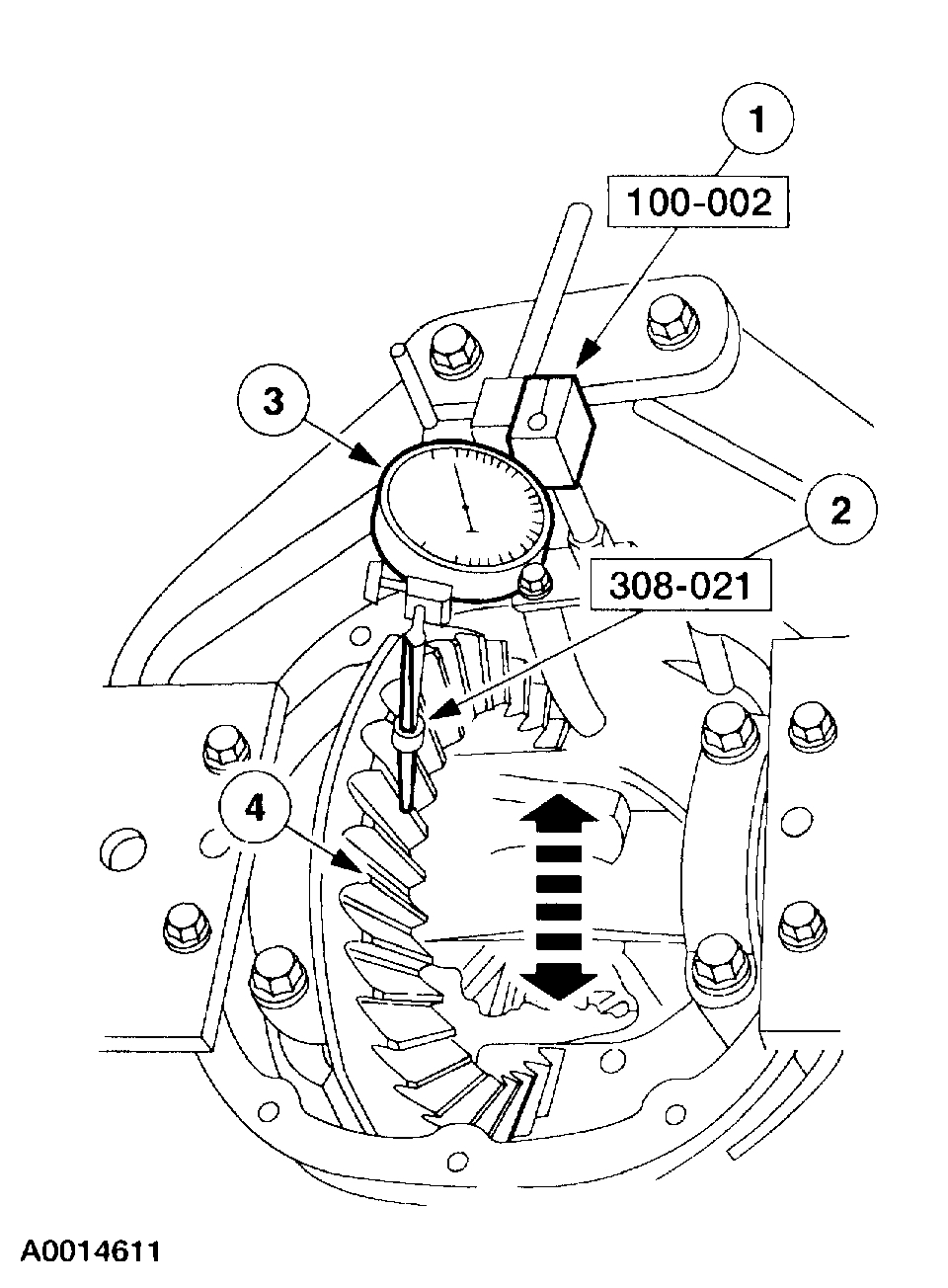
5. CAUTION: Offset the special tool to obtain an accurate reading.
Rotate the special tool several half turns to seat the pinion bearings. Position the special tool as shown.
pic 6
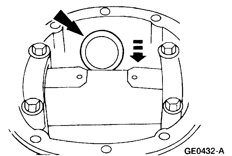
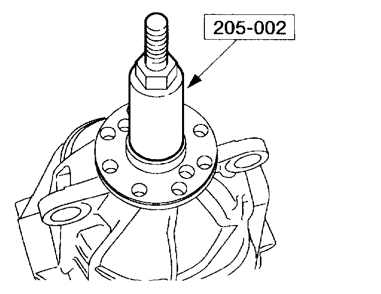
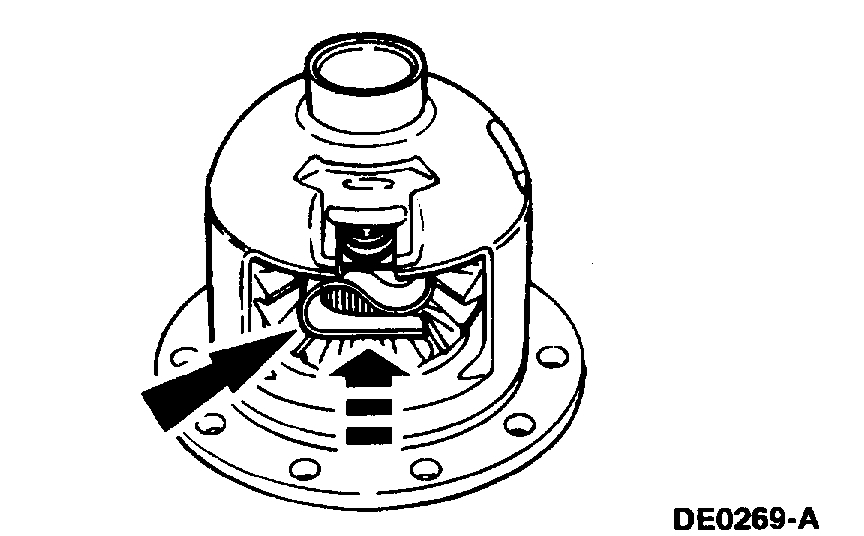
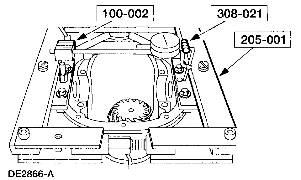
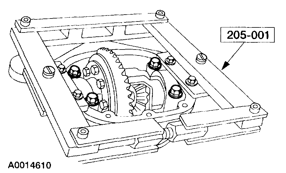
6. Install the special tool.
1 Position the special tool on the differential housing differential bearing seat.
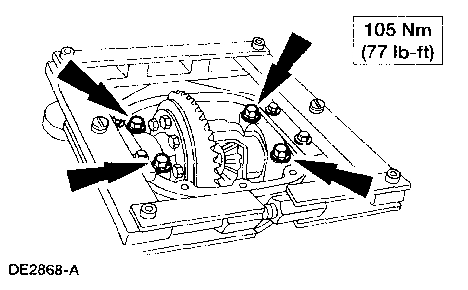
2 Install the differential bearing caps.
3 Install the bolts.
pic 7
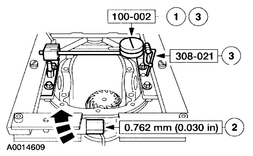
7. Use a drive pinion bearing adjustment shim as a gauge for shim selection. Check the drive pinion bearing adjustment shim thickness between the Gauge Block and the Gauge Tube. A slight drag indicates correct shim selection.
8. Remove all of the special tools.
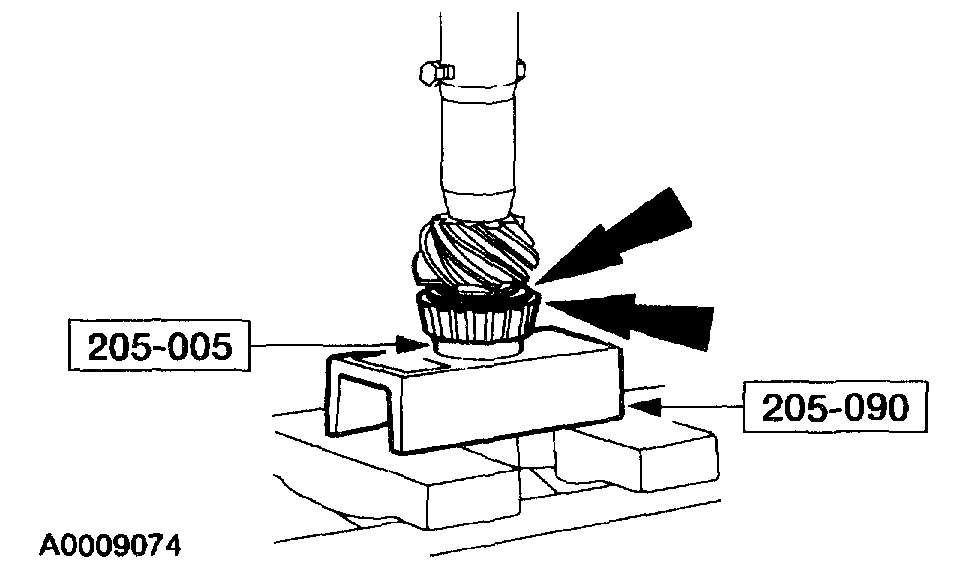
9. CAUTION: Use the same pinion bearings and drive pinion bearing adjustment shim from the drive pinion bearing adjustment shim selection procedure for final assembly.
Position the drive pinion bearing adjustment shim and the pinion bearing on the drive pinion gear stem.
pic 8
10. Using the special tools and a suitable press, firmly seat the drive pinion bearing adjustment shim and pinion bearing on the drive pinion gear stem.
11. Install the front pinion bearing and the rear axle drive pinion shaft oil slinger in the differential housing.
pic 9
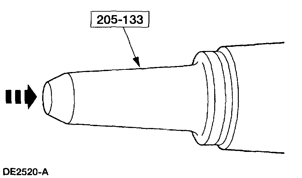
12. CAUTION: Installation without the correct tool can result in early seal failure.
CAUTION: If the seal becomes misaligned during installation, remove it and install a new one.
NOTE: Coat the rear axle drive pinion seal lips with grease.
Using the special tool, install the new rear axle drive pinion seal.
pic 10
13. CAUTION: Make sure the splines on the drive pinion gear stem are free of burrs. If burrs are evident, remove them using a fine crocus cloth, work in a rotational motion.
Place a new differential drive pinion collapsible spacer on the drive pinion gear stem against the pinion stem shoulder.
pic 11
14. Install the drive pinion gear with the differential drive pinion collapsible spacer in the differential housing.
pic 12
15. NOTE: Disregard the index marks if installing a new rear axle pinion flange.
Position the rear axle pinion flange.
1 Lubricate the rear axle pinion flange splines.
2 Position the rear axle pinion flange.
pic 13
16. Using the special tool, install the rear axle pinion flange.
pic 14
17. CAUTION: Do not under any circumstance loosen the nut to reduce preload. If it is necessary to reduce preload, install a new differential drive pinion collapsible spacer and nut.
Tighten the nut to set the preload.
^ Rotate the pinion occasionally to make sure the pinion bearings seat correctly. Take frequent pinion bearing torque preload readings by rotating the drive pinion gear with a Nm (inch/pound) torque wrench.
^ For new pinion bearings, tighten the nut to specification.
^ For used pinion bearings, if the preload recorded prior to disassembly is lower than the specification for used bearings, then tighten the nut to specification.
^ For used pinion bearings, if the preload recorded prior to disassembly is higher than the specification for use bearings, then tighten the nut to the original reading as recorded.
pic 15
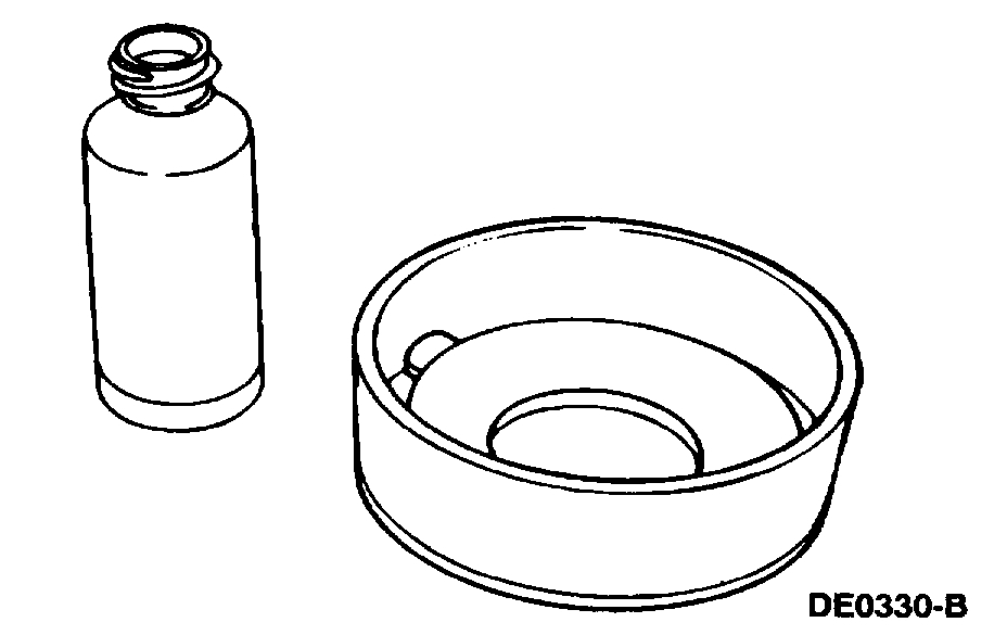
18. CAUTION: 118 ml (4 oz) of Additive Friction Modifier C8AZ-1911546-A or equivalent meeting Ford specification EST-M2C18-A must be used in the axle.
Lubricate each steel clutch plate with additive friction modifier and soak all friction plates for no less than 15 minutes.
pic 16
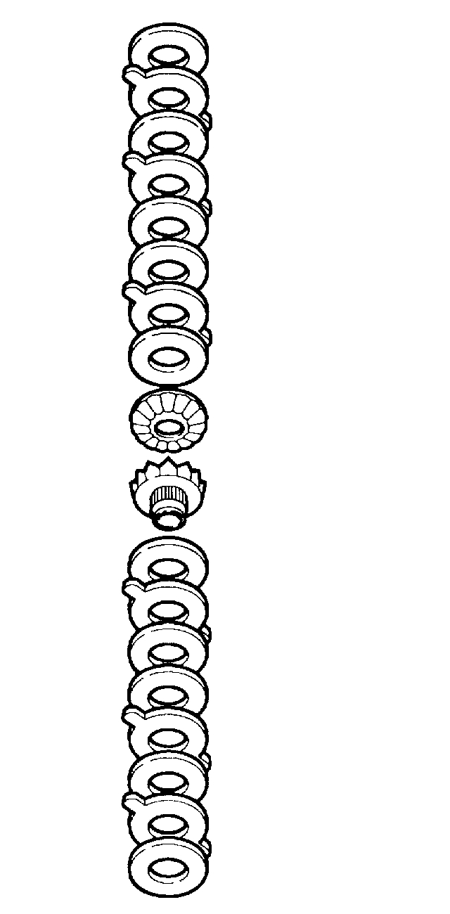
19. CAUTION: Do not mix the clutch plates, clutch discs or shim from one side with the other.
Assemble the differential clutch packs (without the shims) on their respective differential side gear.
pic 17
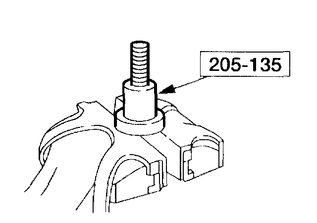
20. Place the base portion of the special tool in a vise.
pic 18
21. Install the differential clutch pack and differential side gear (without the shim) on the special tool.
pic 19
22. Position the special tool hand-tight on top of the differential clutch pack.
pic 20
23. Install the special tool over the disc and differential clutch pack.
pic 22
24. Install the nut.
pic 23
25. Select and insert the thickest feeler gauge blade that will enter between the tool and the differential clutch pack. The reading will be the thickness of the new clutch shim.
pic 24
Selective Shims
26. Remove the special tool from the differential clutch pack and differential side gear assembly.
27. Install the shim(s) on the differential clutch pack and differential side gear assembly.
pic 25
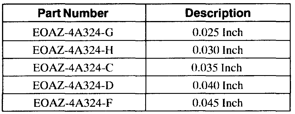
28. Install the differential side gear assemblies in the differential case.
pic 26
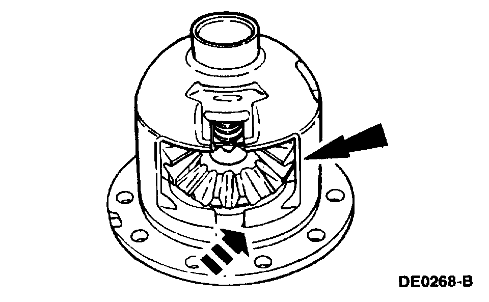
29. Install the differential pinion gear and differential pinion thrust washer assemblies in the differential case.
pic 27
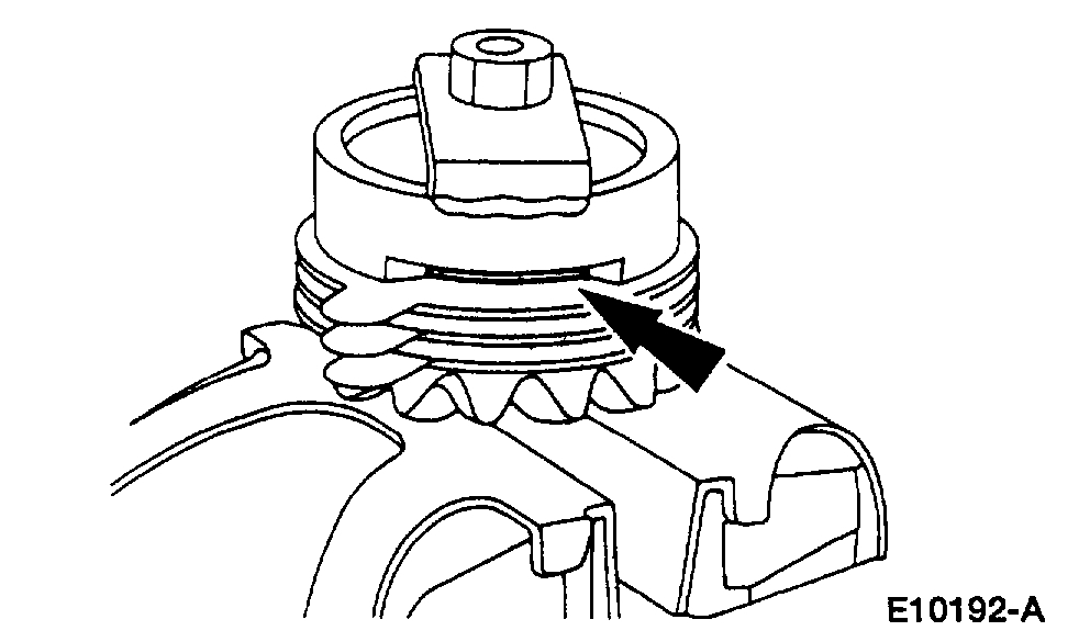
30. Using a soft-faced hammer, install the differential clutch spring.
pic 28
31. NOTE: If a new bolt is unavailable, coat the original bolt threads with Threadlock and Sealer E0AZ-19554-AA or equivalent meeting Ford specification WSK-M2G351-A5 prior to final installation.
Install the differential pinion shaft and install a new bolt finger-tight.
pic 29
32. Mount the differential case and the special tool in a vise. Using the special tool, check the torque necessary to rotate one differential side gear.
If reusing the original clutch plates, the initial minimum break-away torque must be no less than the specification. The minimum rotating torque necessary to keep the differential side gear turning with new clutch plates may vary.
pic 30
33. CAUTION: The master bearings are marked LH and RH. Install them as shown.
Install the special tools on the differential case.
pic 31
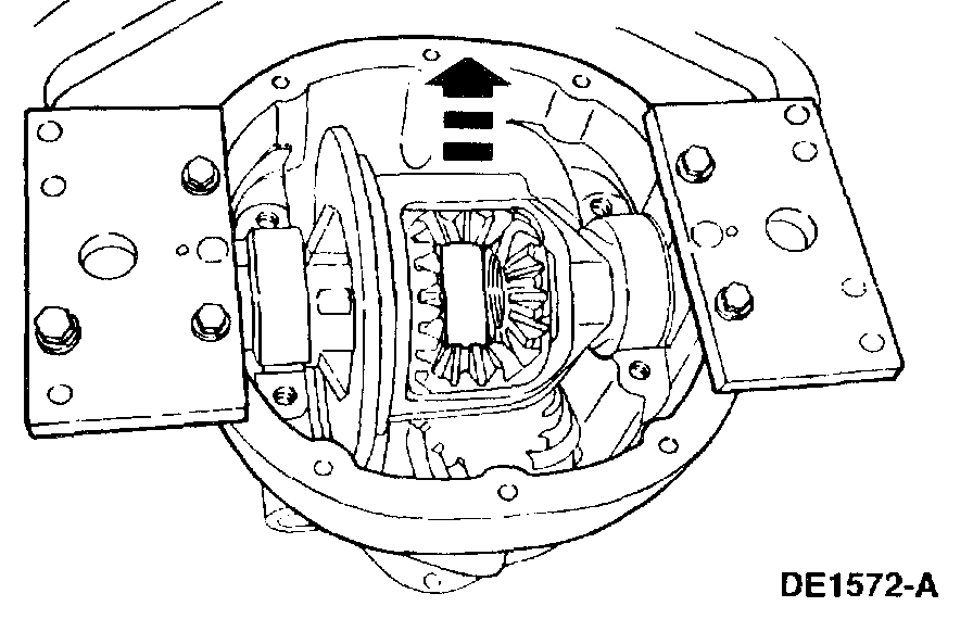
34. CAUTION: Do not damage the aluminum differential housing while carrying out these procedures.
Place the differential case with the special tools in the differential housing.
pic 33
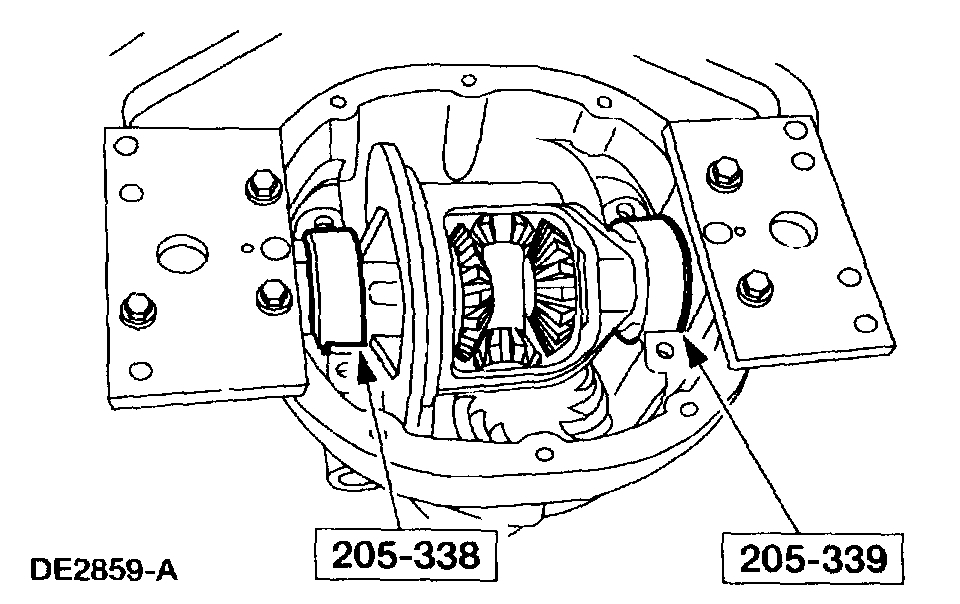
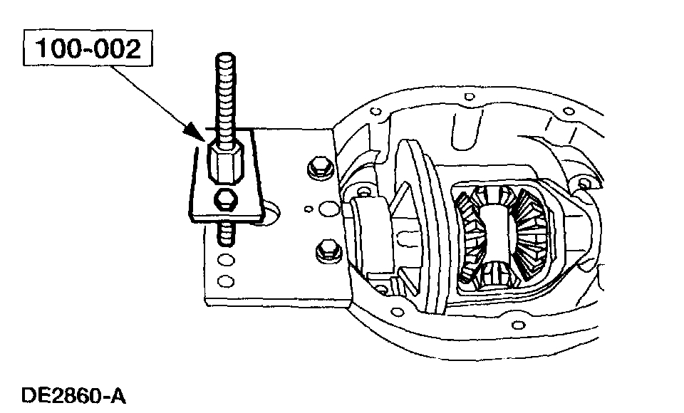
35. Position the special tool on the outside mounting hole.
pic 34
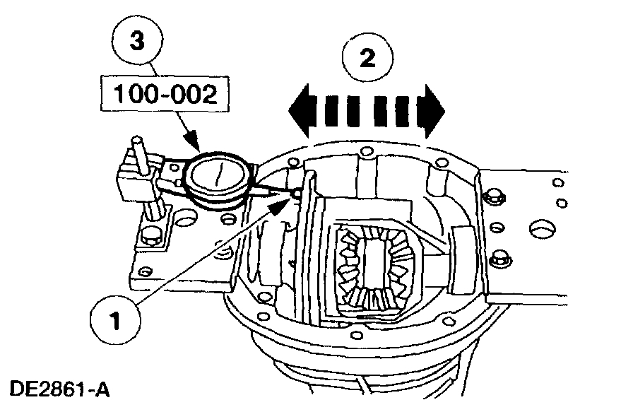
36. NOTE: Repeat this step until obtaining a consistent reading.
Measure the total end play.
1 Attach the special tool and position the indicator tip on the machined surface of the differential case flange.
2 Move the differential case to the left and the right (as far as possible).
3 Record the reading on the differential bearing shim selection procedure line A.
pic 35
pic 36
pic 37
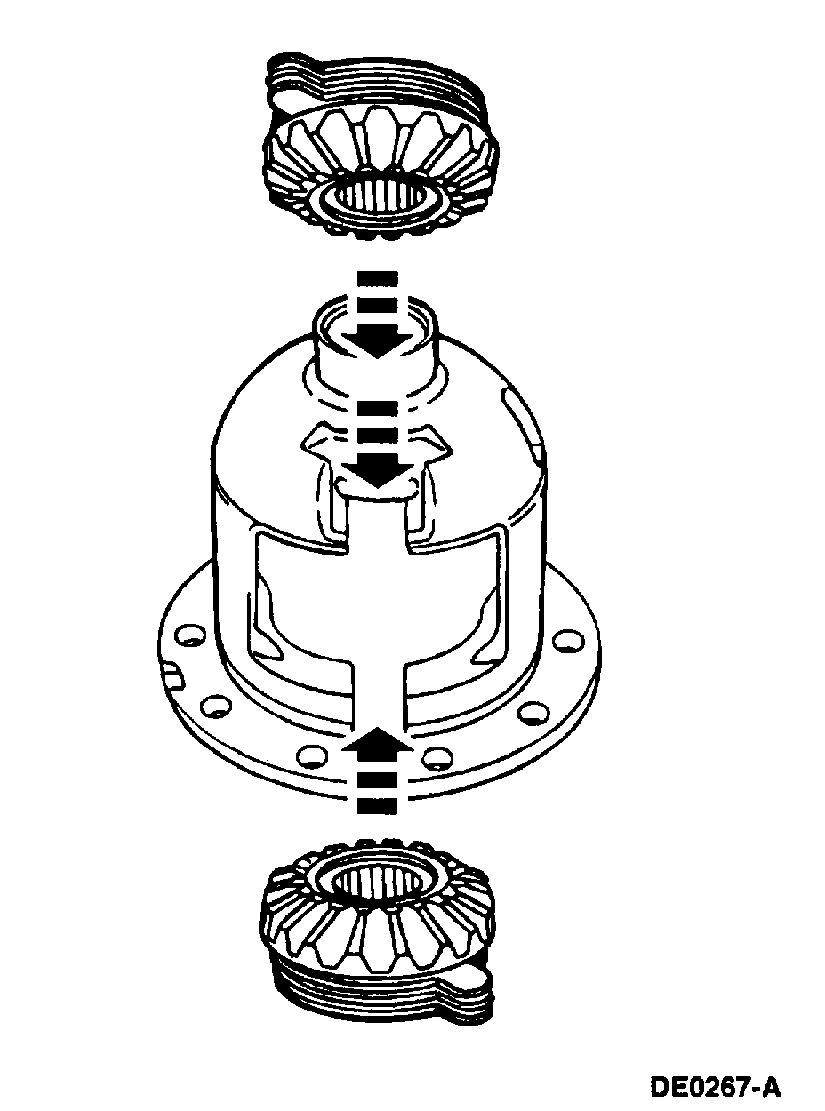
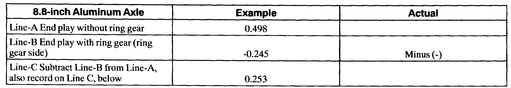
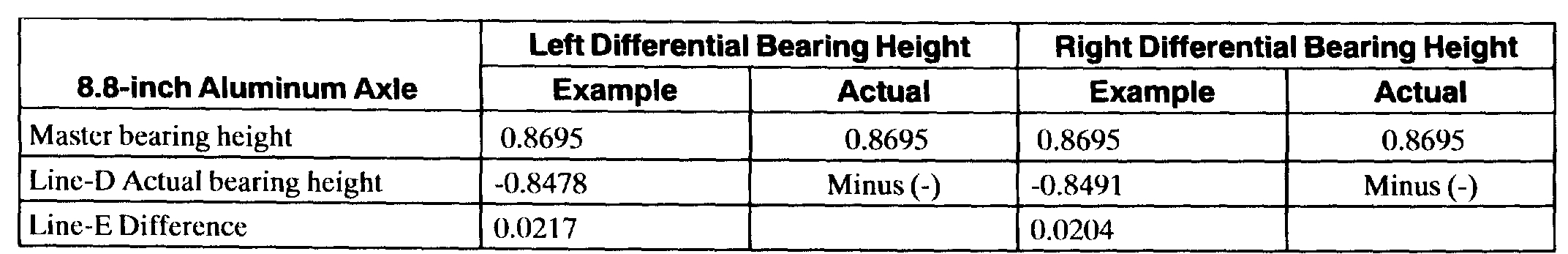
Differential Bearing Shim Selection Chart
pic 38
37. Remove the Dial Indicator and the differential case from the differential housing.
pic 39
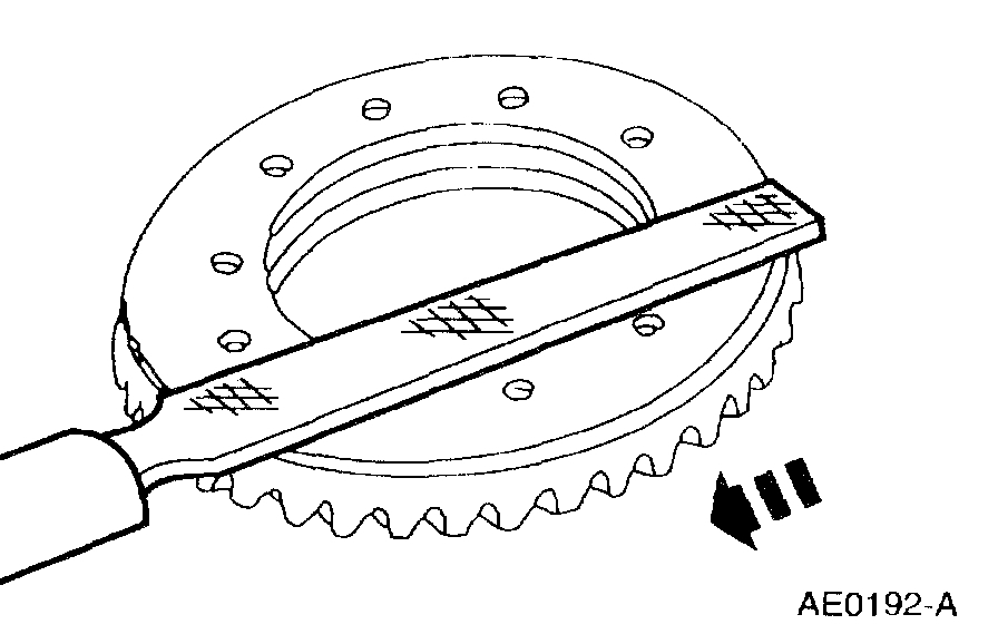
38. Draw-file the differential ring gear mounting surface to remove any nicks or burrs.
pic 40
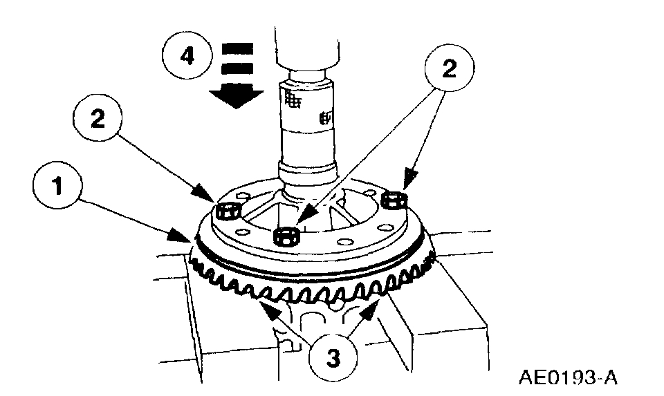
39. Install the differential ring gear.
1 Place the differential ring gear on the differential case.
2 Hand start three bolts to align the holes in the differential ring gear and the differential case.
3 Place the differential case and differential ring gear onto the press bed blocks with the differential ring gear teeth facing downward.
4 Press the differential ring gear into place.
pic 41
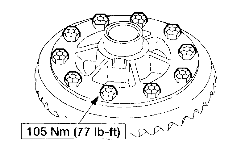
40. Install the remaining bolts.
pic 42
41. Place the differential case with the special tools into the differential housing.
pic 43
42. NOTE: The bolts retaining the differential ring gear to the differential case may interfere while carrying out this procedure. If so, remove three to five bolts to provide clearance.
Measure the end play.
1 Attach the special tool and position the indicator tip on the machined surface of the differential case flange.
2 Rock the differential ring gear to allow full mesh with the drive pinion gear.
3 With the gears in full mesh, set the special tool to zero.
4 Move the differential case as far as possible to the left and note the reading.
5 Record the reading on the differential hearing shim selection procedure line B.
^ Remove the special tool.
pic 44
43. Remove the differential case from the differential housing.
pic 45
44. Remove the bolts. Apply Stud and Bearing Mount EOAZ-19554-BA or equivalent meeting Ford specification WSK-M2G349-A1 to the bolt threads, and reinstall the bolts.
pic 46
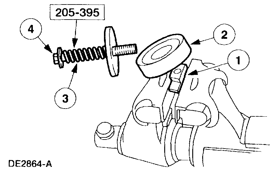
45. NOTE: Measure the stand height of both differential bearings prior to installation.
NOTE: Mark the differential bearings left and right before measuring them.
Install the special tool.
1 Place the special tool base in a soft-jawed vise with the bearing mounting surface above the visejaws.
2 Position the differential bearing on the special tool base.
3 Attach the bolt, spring, washers and spacer.
4 Tighten the bolt.
pic 47
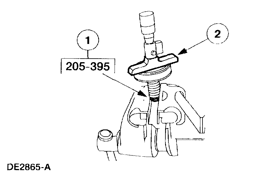
46. Measure the differential bearing stand height.
1 Invert the special tool and clamp the bolt head in a vise.
2 Position a depth micrometer flat on the differential bearing.
47. Measure both differential bearings stand height. Record the measurement on the differential bearing shim selection procedure line D.
pic 48
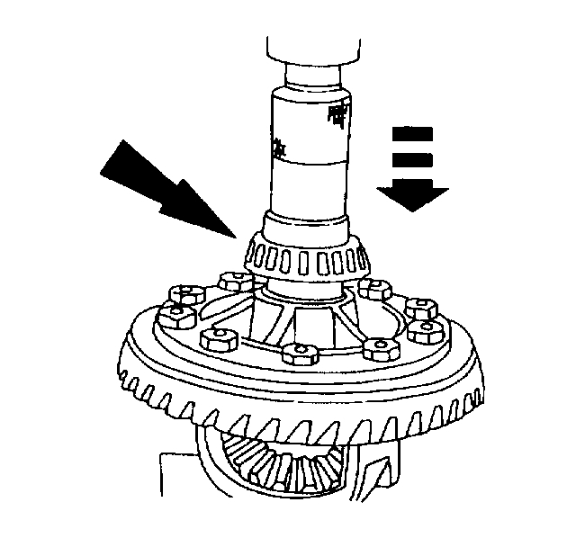
48. Press the left and right differential bearing on the differential case.
pic 49
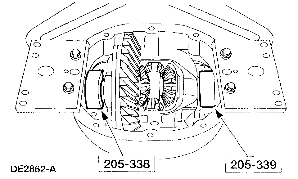
49. Install the special tools.
pic 50
50. CAUTION: Overspreading may damage the differential housing.
NOTE: Tighten and loosen the Differential Carrier Spreader screw to normalize the Housing Spreader Adapters prior to taking the final Dial Indicator reading.
Spread the differential housing to the specification.
1 Adjust the special tool to zero.
2 Tighten the screw until spreading the differential housing to the specification.
3 Remove the special tools.
pic 51
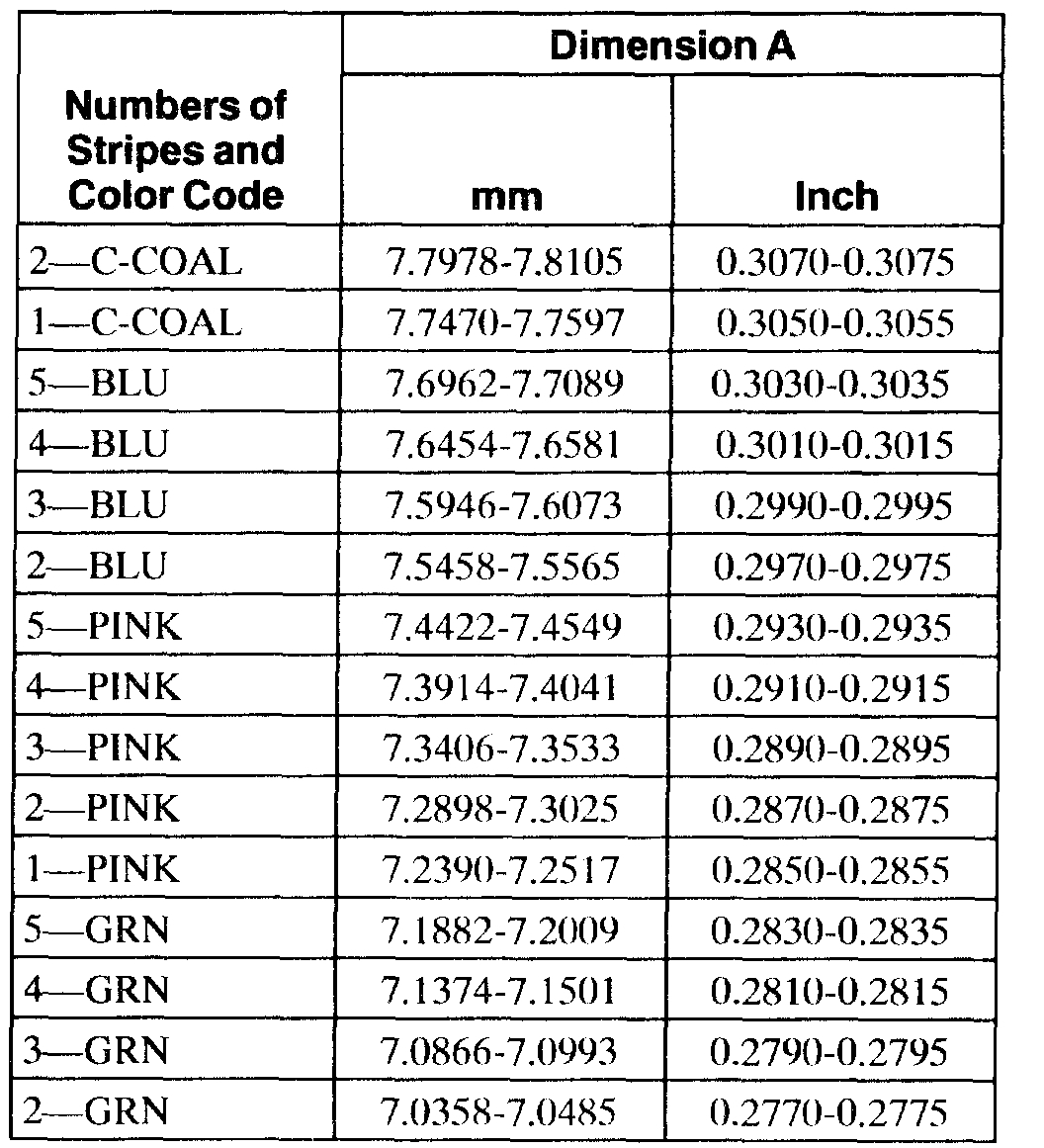
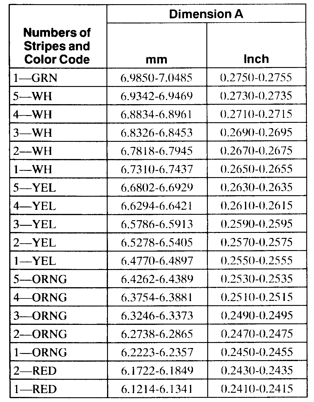
51. NOTE: Select the correct size differential bearing shims by completing the differential bearing shim selection chart.
NOTE: Apply a light coating of grease to the differential bearing shim to help hold in place.
Place the differential bearing shims in the differential housing.
pic 52
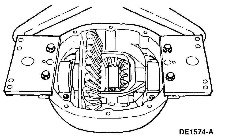
52. Install the differential case.
1 Position the differential bearing cups on the differential bearings.
2 Lower the differential case in place between the differential bearing shims.
pic 53
53. NOTE: Tighten the bolts prior to releasing the carrier spreader.
Install the differential bearing caps in their original locations and positions and tighten the bolts.
pic 54
54. Remove the special tool.
pic 55
55. Install the special tool at the 12 o'clock position.
pic 56
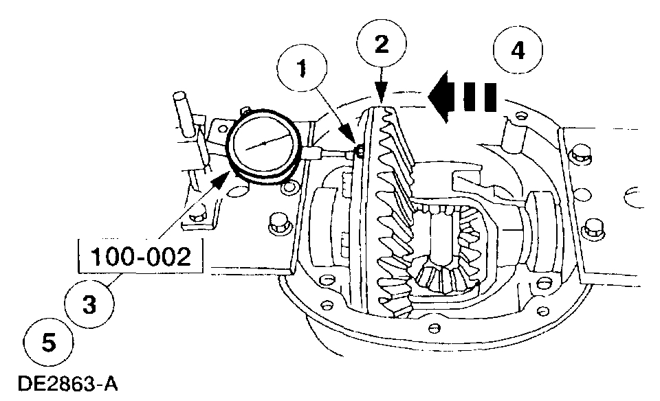
56. Using the special tools, measure the differential ring gear backlash at four equally spaced points.
1 Attach the special tool.
2 Position the special tool tip centrally on a drive tooth.
3 Zero the indicator.
4 Turn the differential ring gear without turning the drive pinion gear. Record the indicator reading. The allowable backlash is 0.203 mm 0.008 inch) to 0.330 mm (0.043 inch) and must not very more than 0.1016 mm (0.004 inch) between points measured. A backlash variation of more than 0.1016 mm (0.004 inch) between points checked indicates gear/case runout.
^ If backlash is within specifications, proceed to Final assembly in this procedure.
^ To correct for a high or low backlash proceed as follows.
pic 57
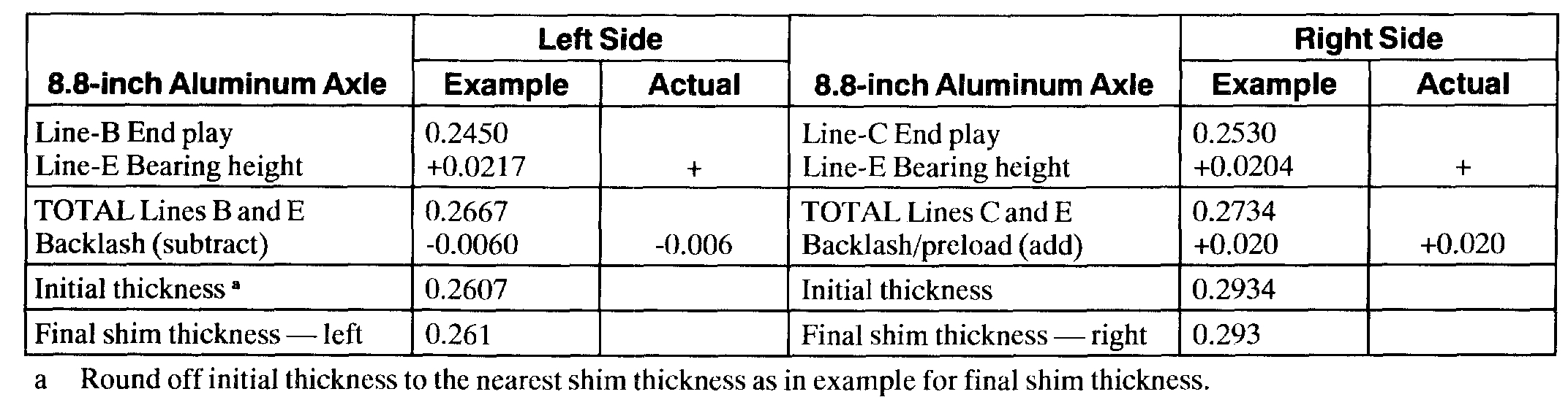
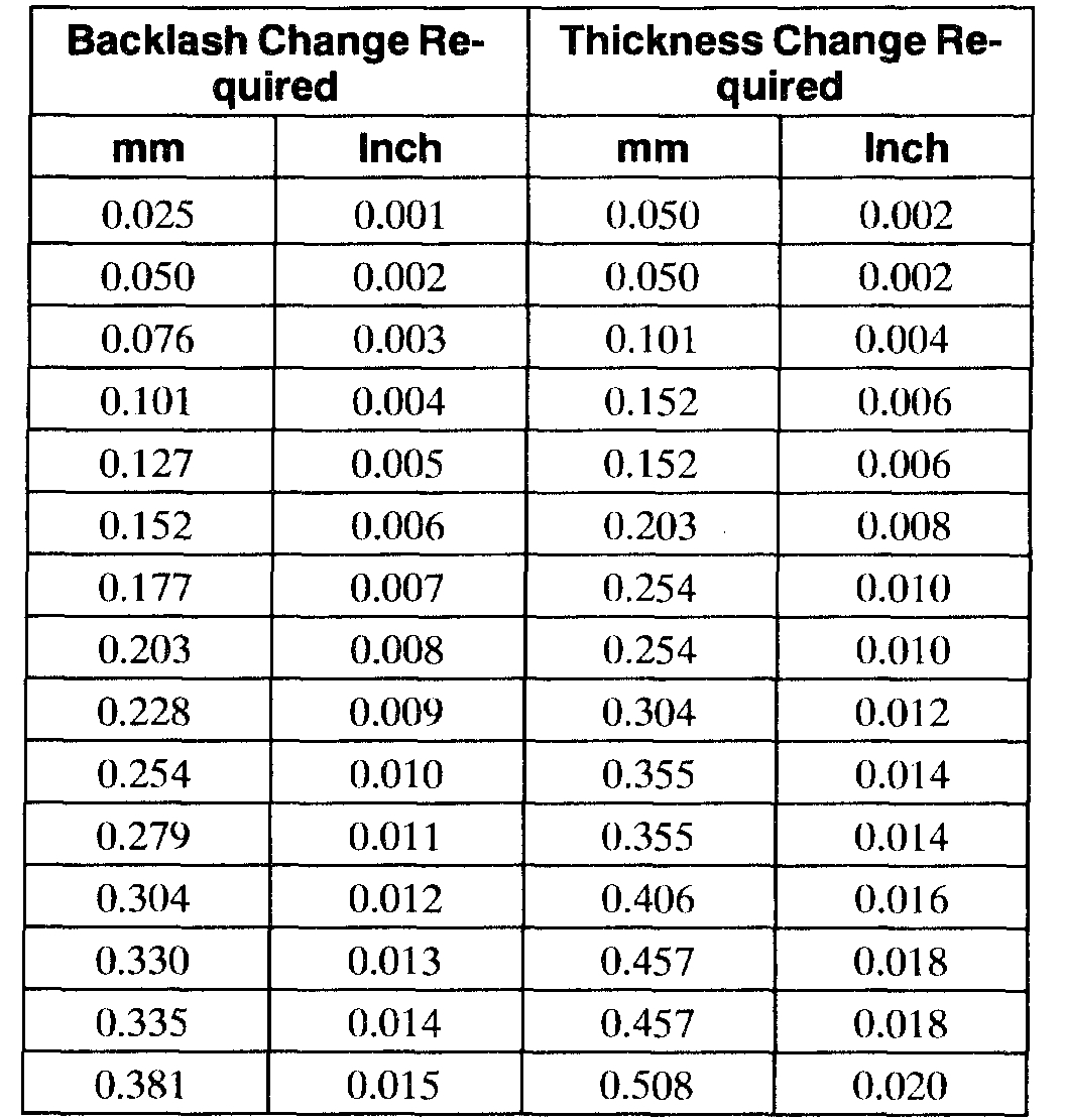
57. To correct for high or low backlash increase the thickness of one differential bearing shim and decrease the thickness of the other differential bearing shim by the same amount. Refer to the following tables when adjusting the backlash. When the backlash is within specifications, proceed to Final assembly.
pic 58
pic 59
Differential Shim Size Chart - 4067 -
pic 60
Final assembly
58. CAUTION: The machined surfaces on the differential housing and the differential housing cover must be clean and free of oil before applying the new silicone sealant. Cover the inside of the axle before cleaning the machined surface to prevent contamination.
CAUTION: Install the differential housing cover within 15 minutes of applying the silicone material.
CAUTION: Allow the sealant to cure for one hour before filling the axle with lubricant.
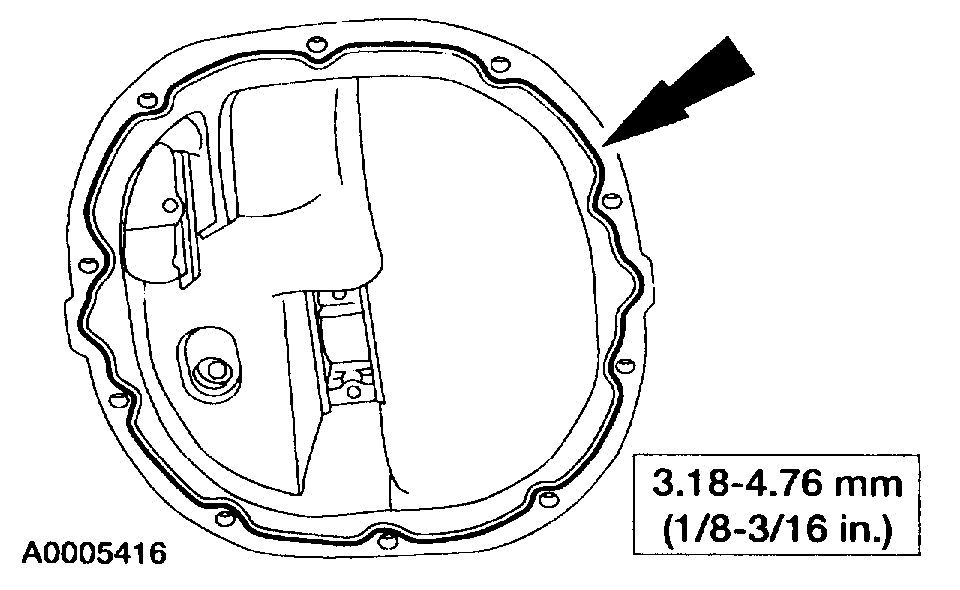
Apply a continuous bead of sealant, of the specified thickness, to the differential housing cover mounting surface.
59. Install the differential housing cover.
60. CAUTION: First fill the rear axle with 118 ml (4 oz) of Additive Friction Modifier C8AZ-19B546-A or equivalent meeting Ford specification EST-M2CII8-A.
Install the rear axle assembly in the vehicle. Fill the axle with the specified lubricant.
__________________________
I hope this helps in some way. Let me know if you have other questions.
Take care,
Joe
Images (Click to enlarge)
Jul 13, 2019 at 11:34 PM