Hi,
The air flow directions is determined by what is called a mode air door actuator. The actuator isn't the easiest thing to replace. However, here are the directions for replacement. You will need to remove the brake pedal and bracket to access it.
____________________________________
2015 Ford Truck Explorer 4WD V6-3.5L
Mode Door Actuator - Defrost/Panel/Floor Door
Vehicle Heating and Air Conditioning Air Door Actuator / Motor Service and Repair Removal and Replacement Dual Automatic Temperature Control (DATC) Mode Door Actuator - Defrost/Panel/Floor Door
MODE DOOR ACTUATOR - DEFROST/PANEL/FLOOR DOOR
412-00A Climate Control — DATC 2015 Explorer
REMOVAL AND INSTALLATION
Mode Door Actuator — Defrost/Panel/Floor Door
Removal
Remove the brake pedal and bracket assembly. REFER to Section 206-06A, Brake Pedal and Bracket .
Remove the IPC . REFER to Section 413-01, Instrument Panel Cluster (IPC) .
NOTE: The upper rear mode door actuator screw can be accessed through the instrument cluster opening using a swivel-type socket and extension.
Remove the 3 defrost/panel/floor mode door actuator screws.
Disconnect the defrost/panel/floor mode door actuator electrical connector.
Remove the defrost/panel/floor mode door actuator.
Installation
To install, reverse the removal procedure.
___________________________________
Here are the directions for removing the brake pedal and bracket. The attached pic correlates with the directions.
__________________________________
2015 Ford Truck Explorer 4WD V6-3.5L
Brake Pedal and Bracket
Brake Pedal and Bracket
BRAKE PEDAL AND BRACKET
206-06A Hydraulic Brake Actuation 2015 Explorer
REMOVAL AND INSTALLATION
Brake Pedal and Bracket
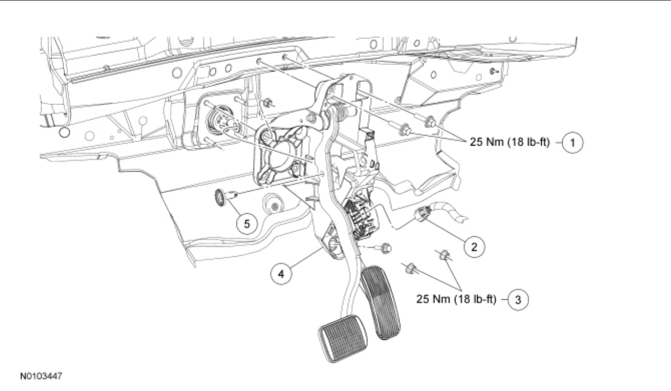
Exploded View
pic 1
Item Service Part Number Description Torque Material Name Notes
1 W709633 Brake pedal bracket bolts (3 required) - - 25 Nm (18 lb-ft)
2 - Accelerator pedal sensor electrical connector (part of 14401) - - -
3 W520112 Brake booster nuts (4 required) - - 25 Nm (18 lb-ft)
4 9F856 Brake pedal and bracket assembly - - -
5 2L523 Brake booster push rod clevis pin - - -
Removal
If equipped with adjustable pedals, make sure they are in the full forward position.
Remove the steering column. REFER to Section 211-04, Steering Column
Disconnect the accelerator pedal sensor electrical connector and detach the wire harness from the brake pedal assembly.
NOTICE: Do not service the brake pedal or brake booster without first removing the stoplamp switch. The switch must be removed with the brake pedal in the at-rest position. The switch plunger must be compressed for the switch to rotate in the bracket. Attempting to remove the switch when the plunger is extended (during pedal apply) will result in damage to the switch.
Remove the stoplamp switch. REFER to Section 417-01, Stoplamp Switch
NOTE: The booster push rod clevis locking pin is a one-time use only part. Any time the pin is removed, a new one must be installed.
NOTE: An 11 mm, 12-point socket or wrench can be used to compress the 2 tabs on the locking pin.
Remove and discard the booster push rod locking pin.
Remove the 4 brake booster nuts.
Position the brake booster forward enough to allow the brake booster studs to clear the brake pedal assembly.
If equipped with ambient lighting, remove the retainer and position aside the LF footwell lamp.
Remove the lower brake pedal bracket bolt, under the accelerator pedal, from the brake pedal bracket assembly.
Remove the upper 2 brake pedal bracket bolts from the brake pedal bracket assembly.
Disconnect the vehicle electrical harness locators and remove the brake pedal bracket assembly from the vehicle.
Installation
Install the brake pedal bracket assembly and the 2 upper bolts.
Tighten to 25 Nm (18 lb-ft).
Install the lower brake pedal bracket assembly bolt under the accelerator pedal.
Tighten to 25 Nm (18 lb-ft).
Install the 4 brake booster nuts.
Tighten to 25 Nm (18 lb-ft).
If equipped with ambient lighting, position back the LF footwell lamp and install the retainer.
Install the new booster push rod locking pin.
NOTICE: Do not press, pull or otherwise move the brake pedal while installing the stoplamp switch. The switch must be installed with the booster push rod attached to the brake pedal and with the brake pedal in the at-rest position. Installing the switch with the brake pedal in any other position will result in incorrect adjustment and may damage the switch.
Install the stoplamp switch. REFER to Section 417-01, Stoplamp Switch
Connect the accelerator pedal sensor electrical connector, the adjustable pedal motor electrical connector (if equipped) and attach the wire harness to the brake pedal assembly.
Connect the vehicle electrical harness locators to the brake pedal bracket assembly.
Install the steering column. REFER to Section 211-04, Steering Column
_________________________________
Here are the directions for removal of the instrument panel cluster (IPC). The remaining pics correlate with the directions.
_________________________________
2015 Ford Truck Explorer 4WD V6-3.5L
Instrument Panel Cluster (IPC)
Instrument Panel Cluster (IPC)
INSTRUMENT PANEL CLUSTER (IPC)
413-01 Instrumentation, Message Center, and Warning Chimes 2015 Explorer
REMOVAL AND INSTALLATION
Instrument Panel Cluster (IPC)
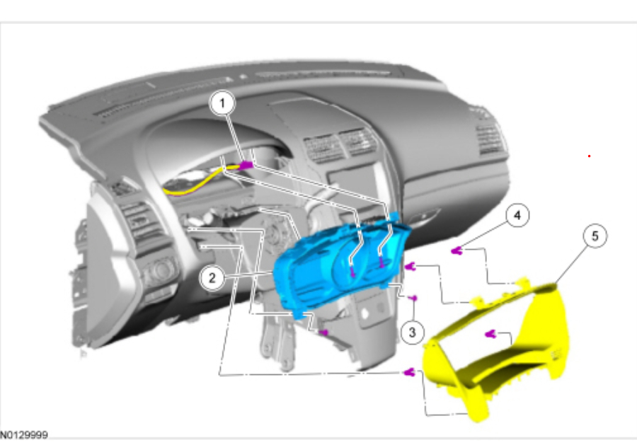
Exploded View
NOTE: Steering wheel shown removed for clarity.
pic 2
Item Service Part Number Description Torque Material Name Notes
1 - IPC electrical connector (part of 14401) - - -
2 10849 IPC - - -
3 W707628 IPC screws (4 required) 3 Nm (27 lb-in) - -
4 W710338 IPC trim panel clip - - -
5 78044D70 IPC trim panel - - -
Removal
NOTE: If installing a new module, it is necessary to upload the module configuration information to the scan tool prior to removing the module. This information must be downloaded into the new module after installation.
Upload the module configuration information from the IPC module into the scan tool following the scan tool on screen instructions.
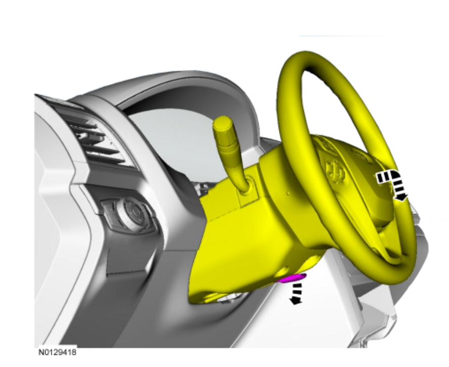
Position the steering wheel to the full downward and outward postion.
pic 3
Unclip the gap hider from the upper steering column shroud.
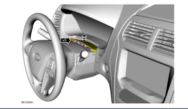
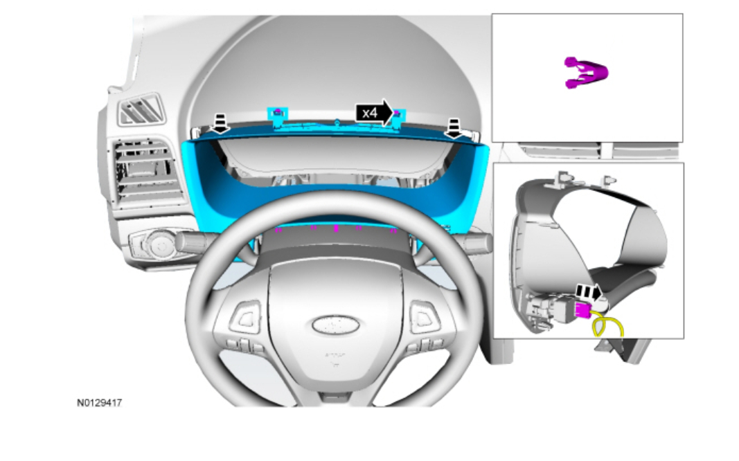
pic 4
Release the 4 clips and remove the IPC bezel.
Disconnect the electrical connector.
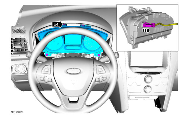
pic 5
Remove the 4 IPC screws and remove the IPC .
To install, tighten to 3 Nm (27 lb-in).
Disconnect the electrical connector.
pic 6
Installation
To install, reverse the removal procedure.
_________________________________________________
As mentioned, this isn't an easy one to do. However, if you have questions or need help, let me know.
Take care,
Joe
Images (Click to enlarge)
Jan 25, 2020 at 9:01 PM