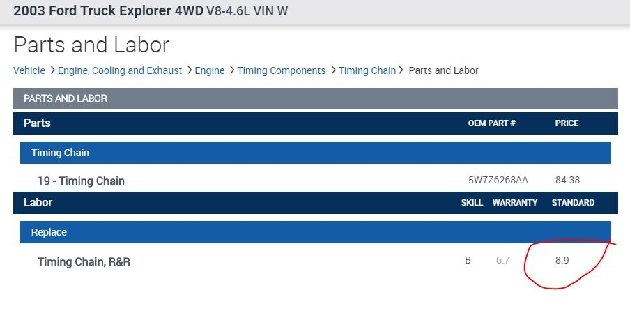
As far as the labor for removal and replacement of the timing chain, the total job calls for 8.9 hours. Check out the diagrams (Below). Please let us know if you need anything else to get the problem fixed.
I can provide the directions for removal and replacement if you want to do it yourself. Here are the directions. The attached pictures correlate with the directions. It is extensive, but if you take your time, you should be okay. Even if you chose not to do it, the directions will help with removing the head. If you do decide to do it, I recommend replacing the chains, tensioners, and all related components at the same time.
Engine Front Cover, Timing Gears, Chain and Tensioners
Removal and Installation
CAUTION: Since the engine is not free - wheeling, timing procedures must be followed exactly or piston and valve damage can occur.
1. Drain the cooling system.
2. Remove the front crankshaft seal.
3. Remove the roller followers.
4. Drain the engine oil.
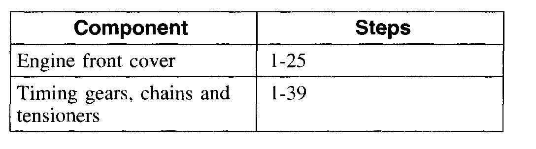
5. To remove individual components, carry out only the listed steps.
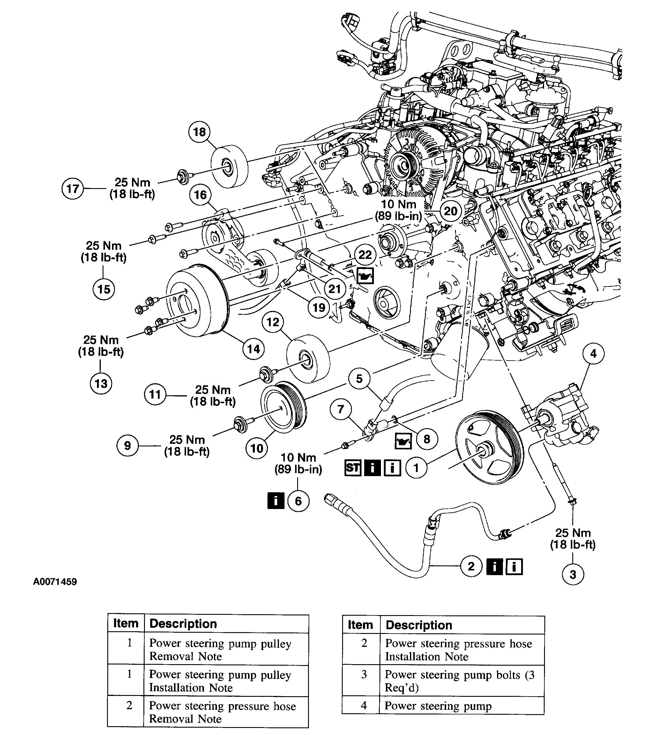
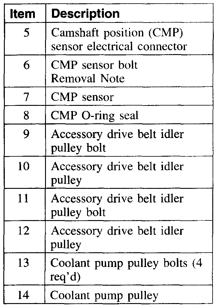
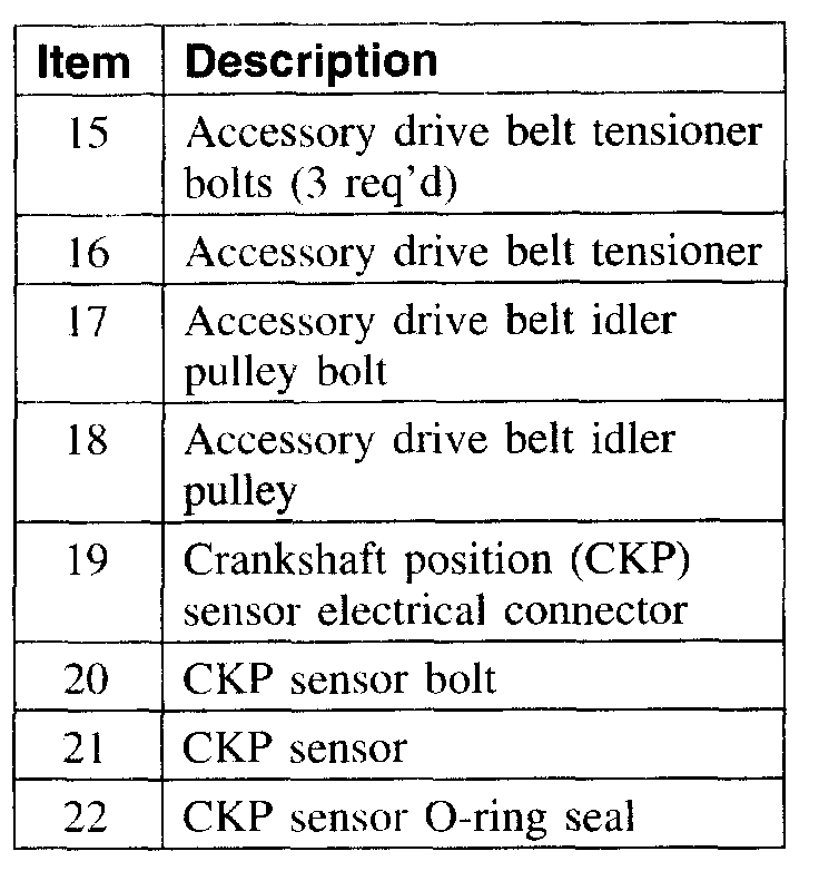
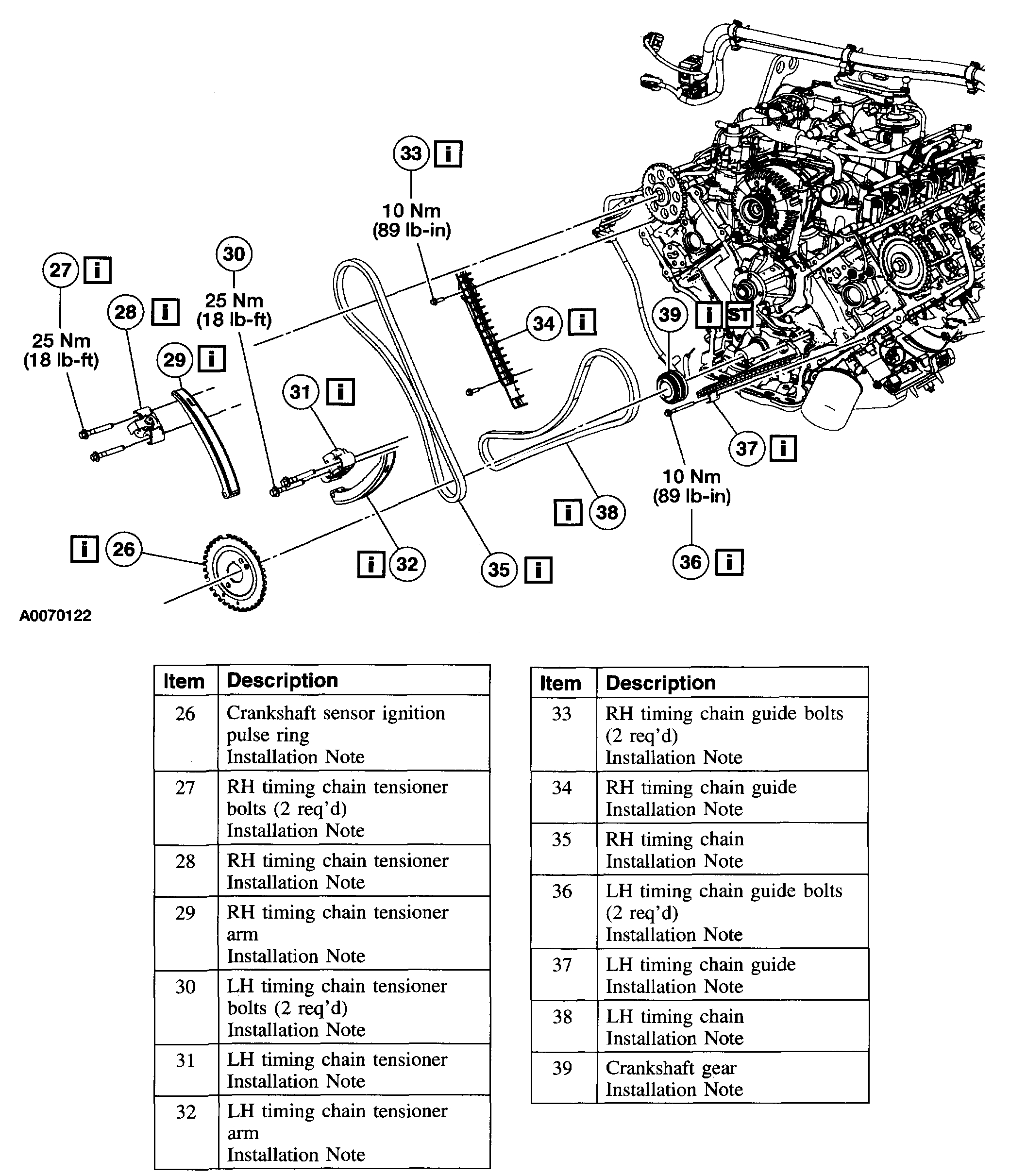
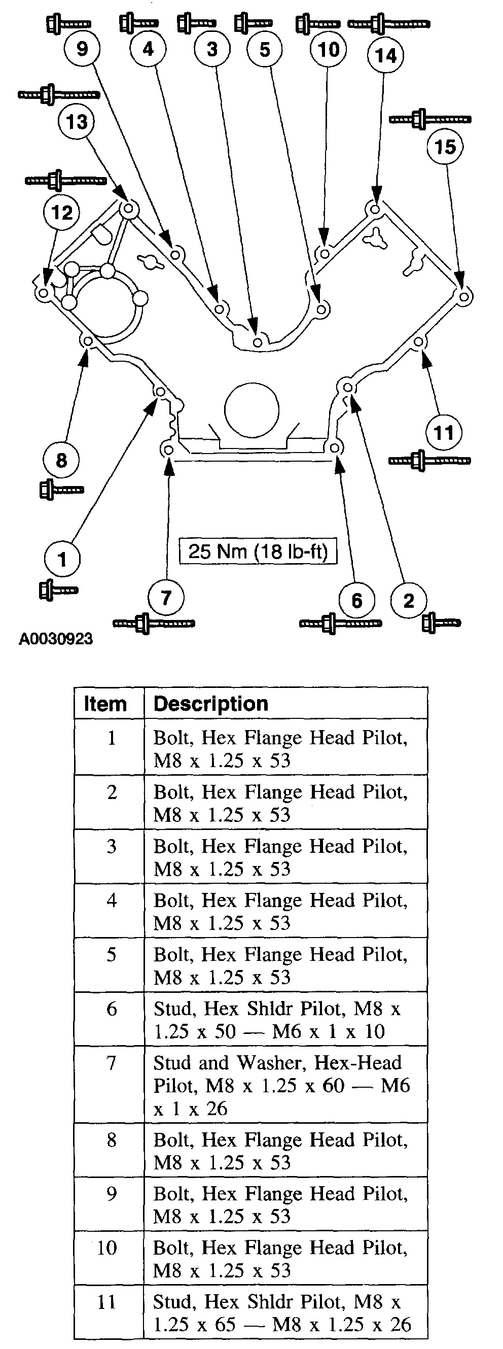
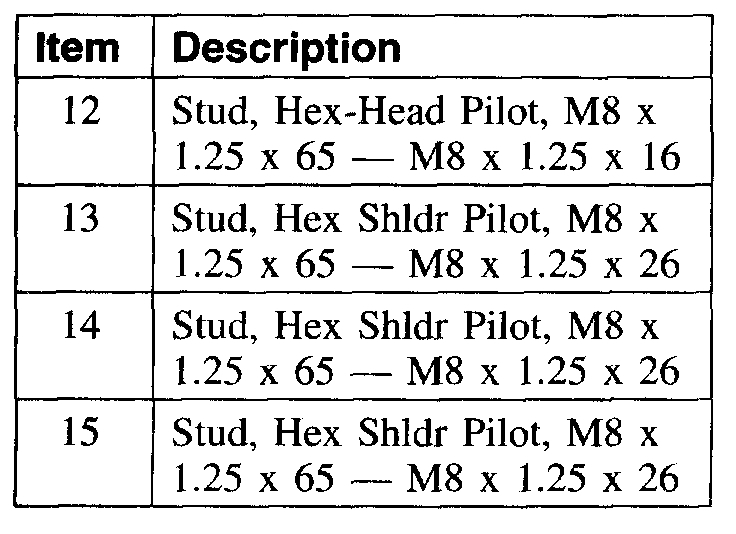
6. Illustration 1 of 3. Remove the components in the order indicated.
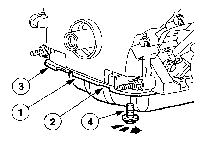
7. illustration 2 of 3. Remove the components in the order indicated.
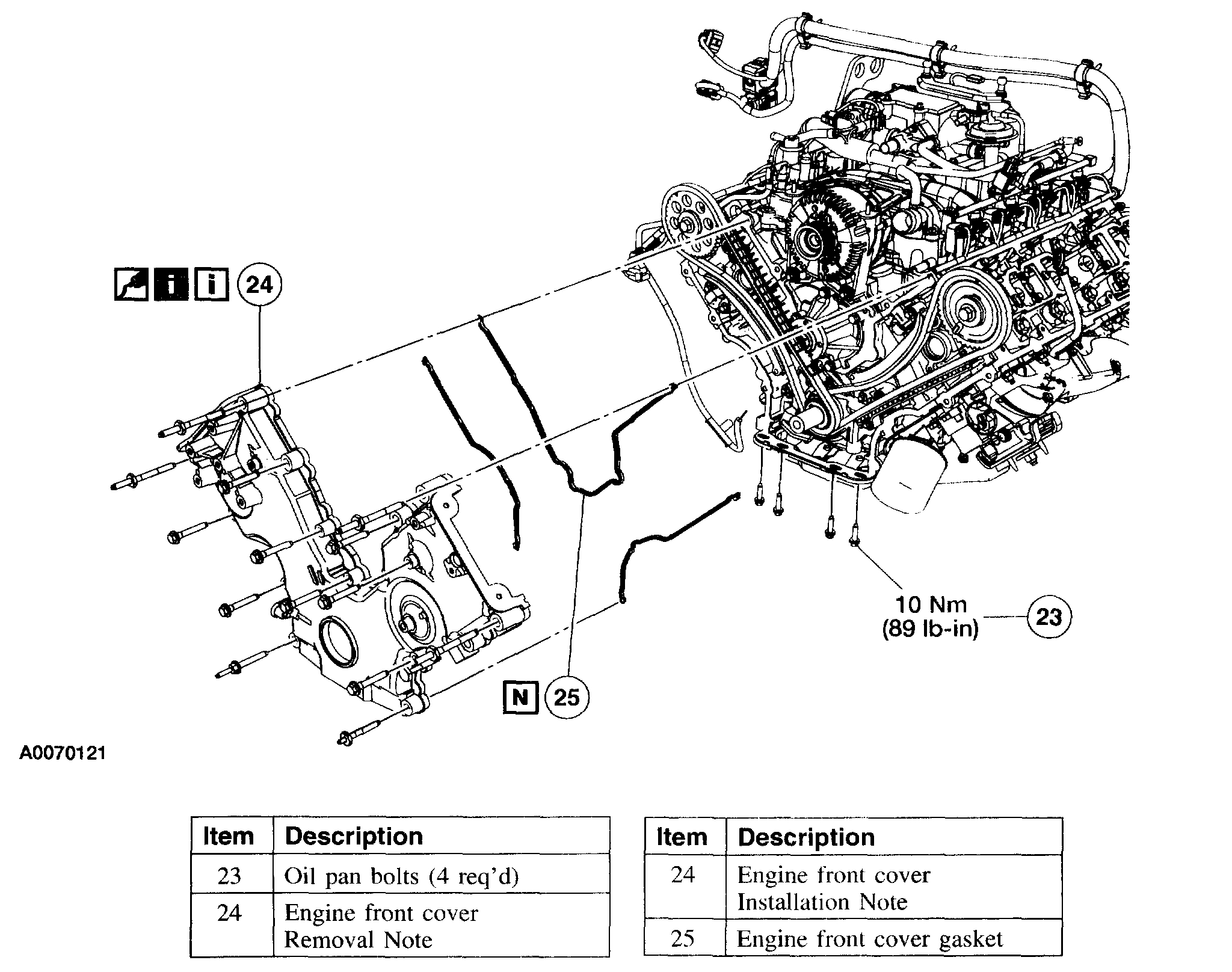
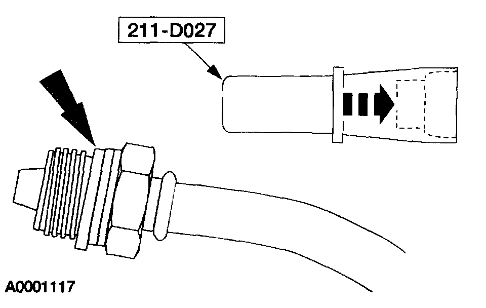
8. Illustration 3 of 3. Remove the components in the order indicated.
9. To install, reverse the removal procedure.
10. Fill the engine with clean engine oil.
11. Fill and bleed the engine cooling system.
12. Install the roller followers.
13. Fill and bleed the power steering system.
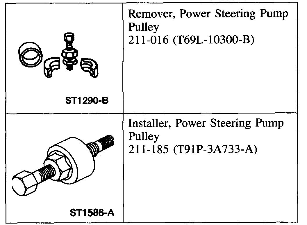
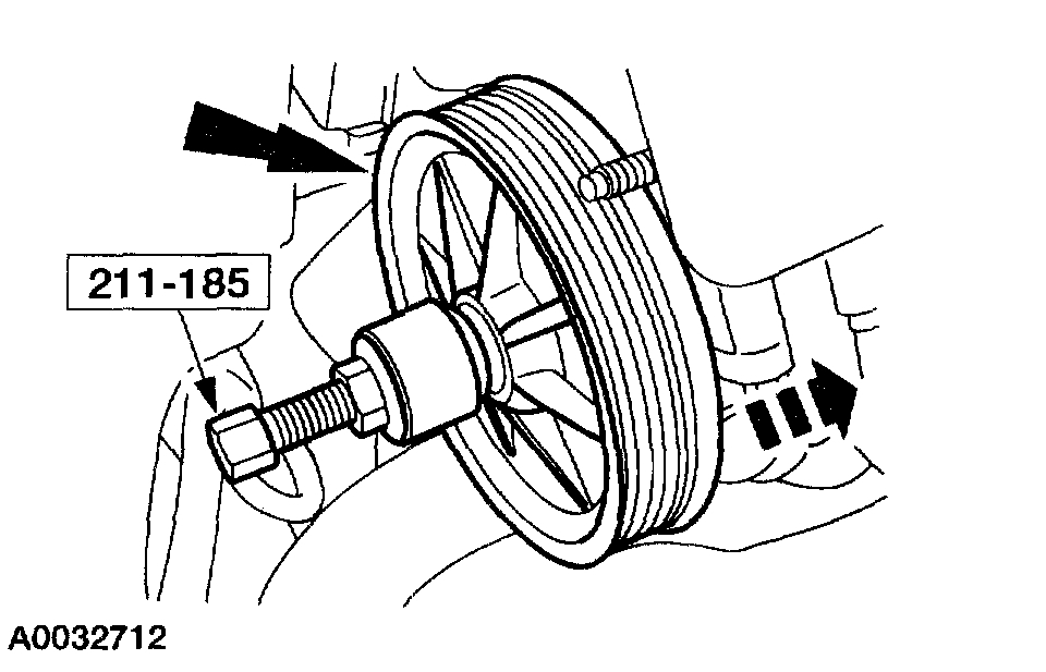
Item 1: Power Steering Pump Pulley Removal Note
1. CAUTION: While servicing the power steering system, make sure to plug all open hoses, line fittings, and fluid ports to prevent the entry of contaminants, or premature failure of power steering components can result.
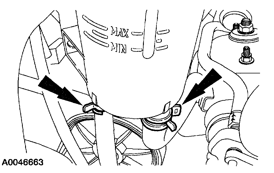
Remove the power steering reservoir bolts.
2. Loosen the clamps, disconnect the hoses and remove the reservoir.
^ Drain the fluid into a suitable container.
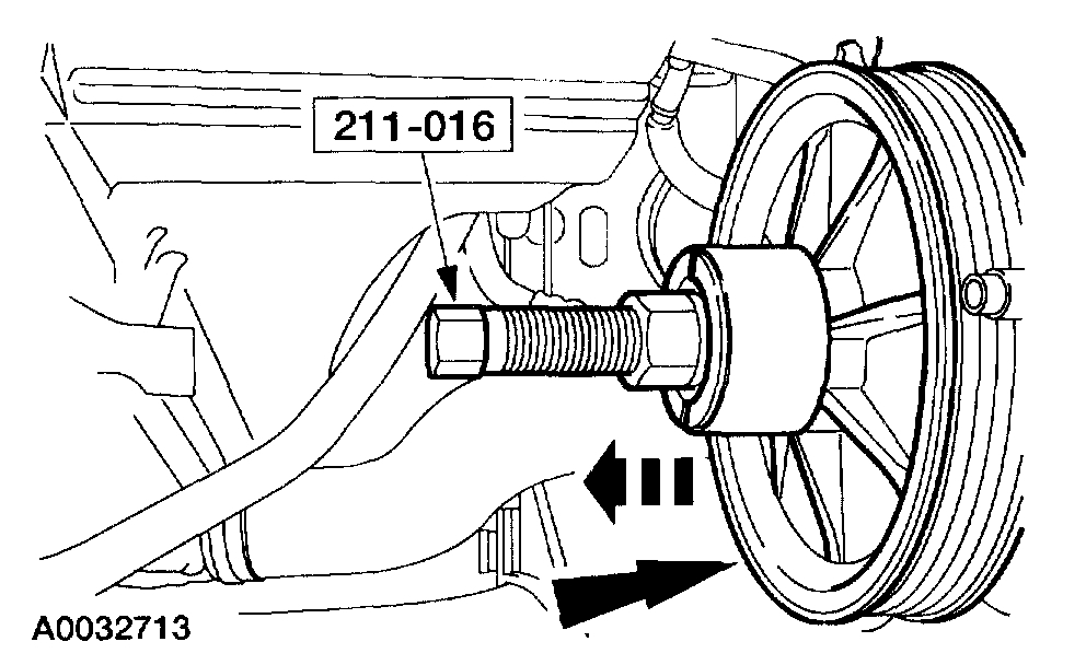
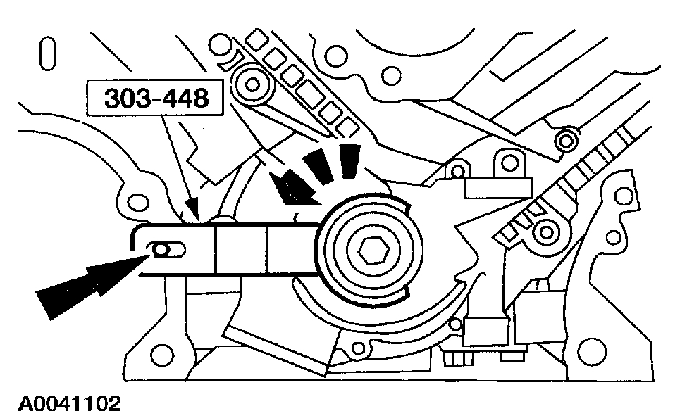
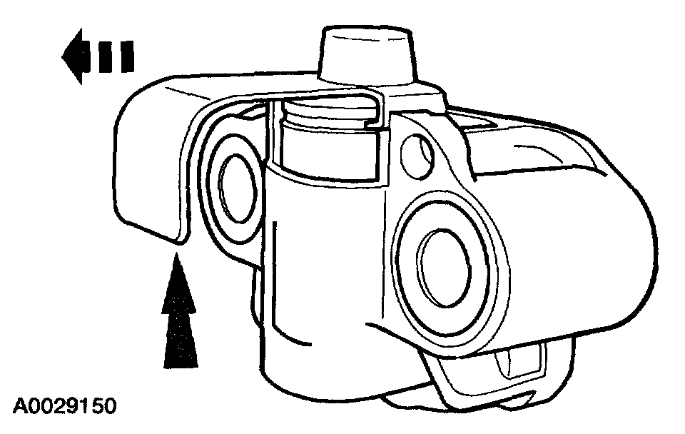
3. Using the special tool, remove the power steering pump pulley.
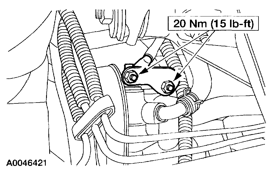
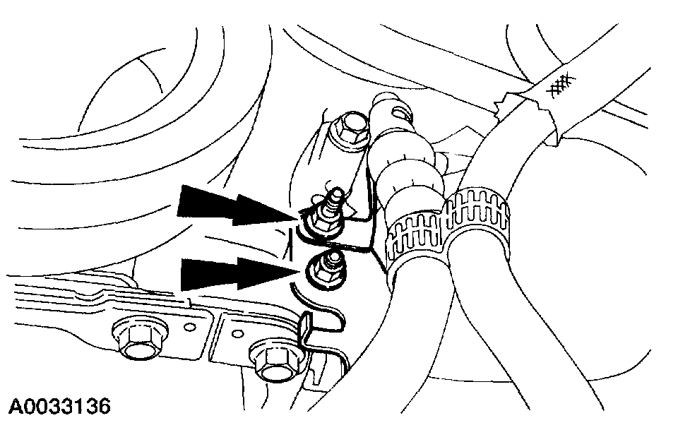
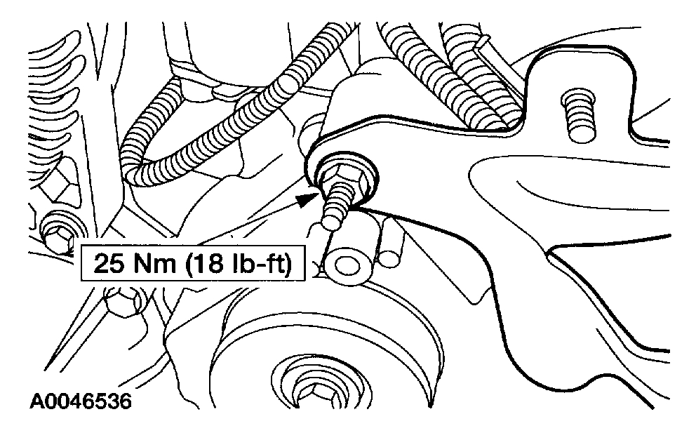
4. Remove the nuts and position the wiring bracket out of the way.
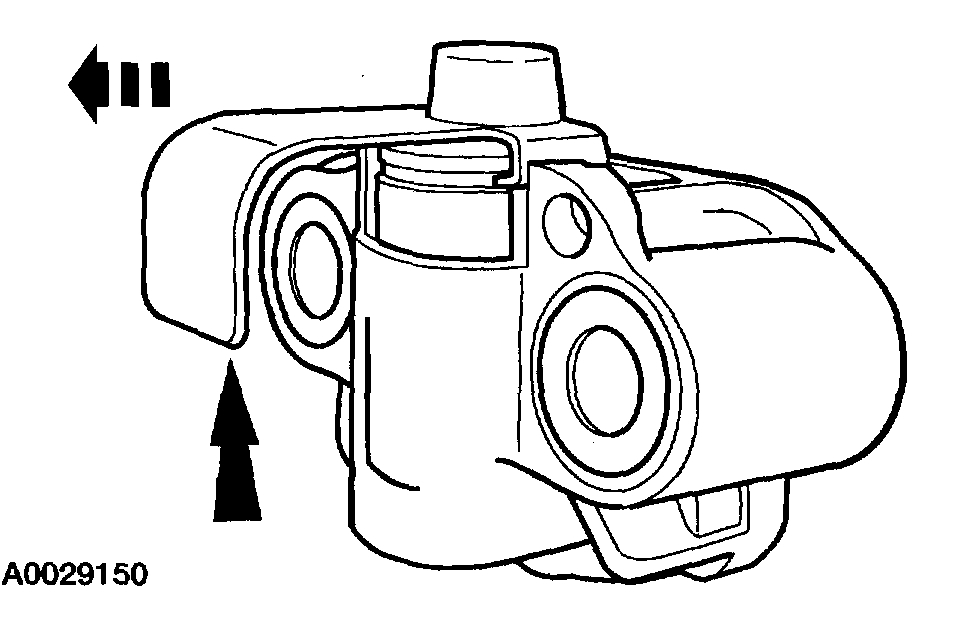
Item 2: Power Steering Pressure Hose Removal Note
1. Remove the brackets.
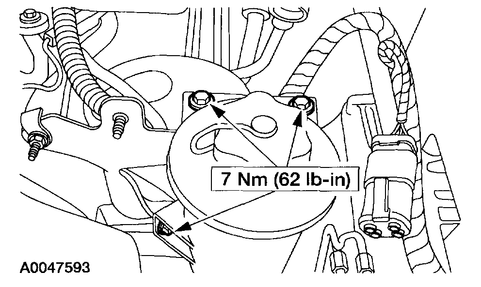
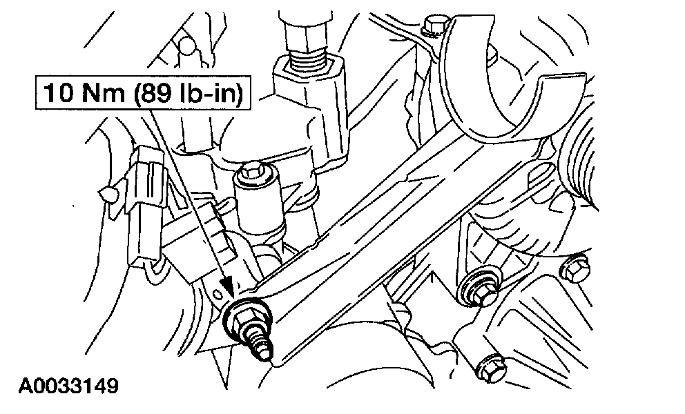
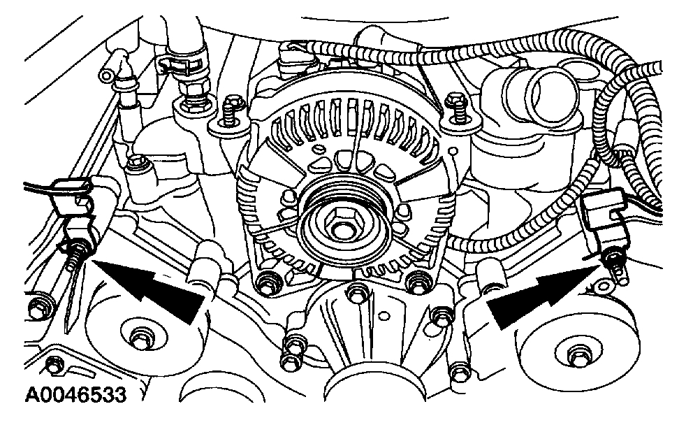
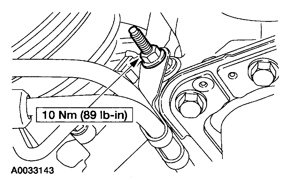
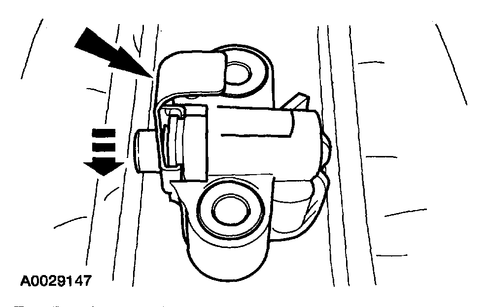
Item 6: Camshaft Position (CMP) Sensor Bolt Removal Note
1. Remove the upper radiator hose bracket.
2. Remove the radio capacitors.
3. Remove the power steering reservoir bracket.
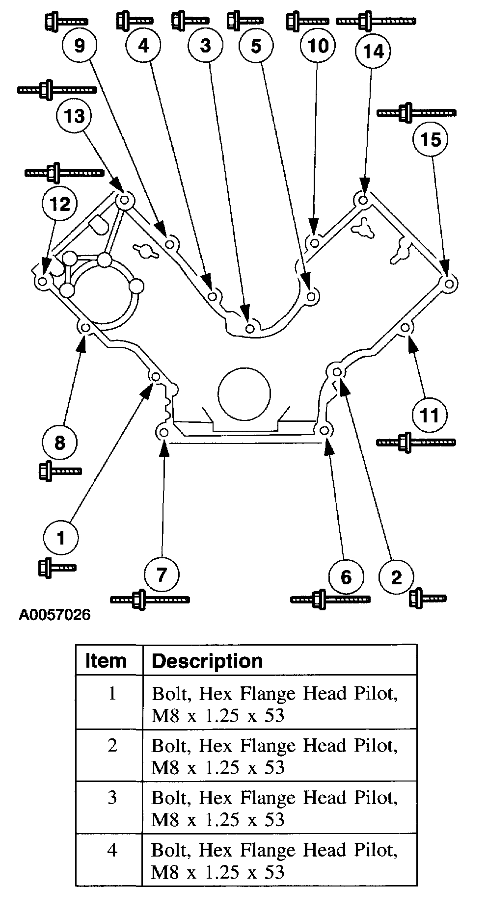
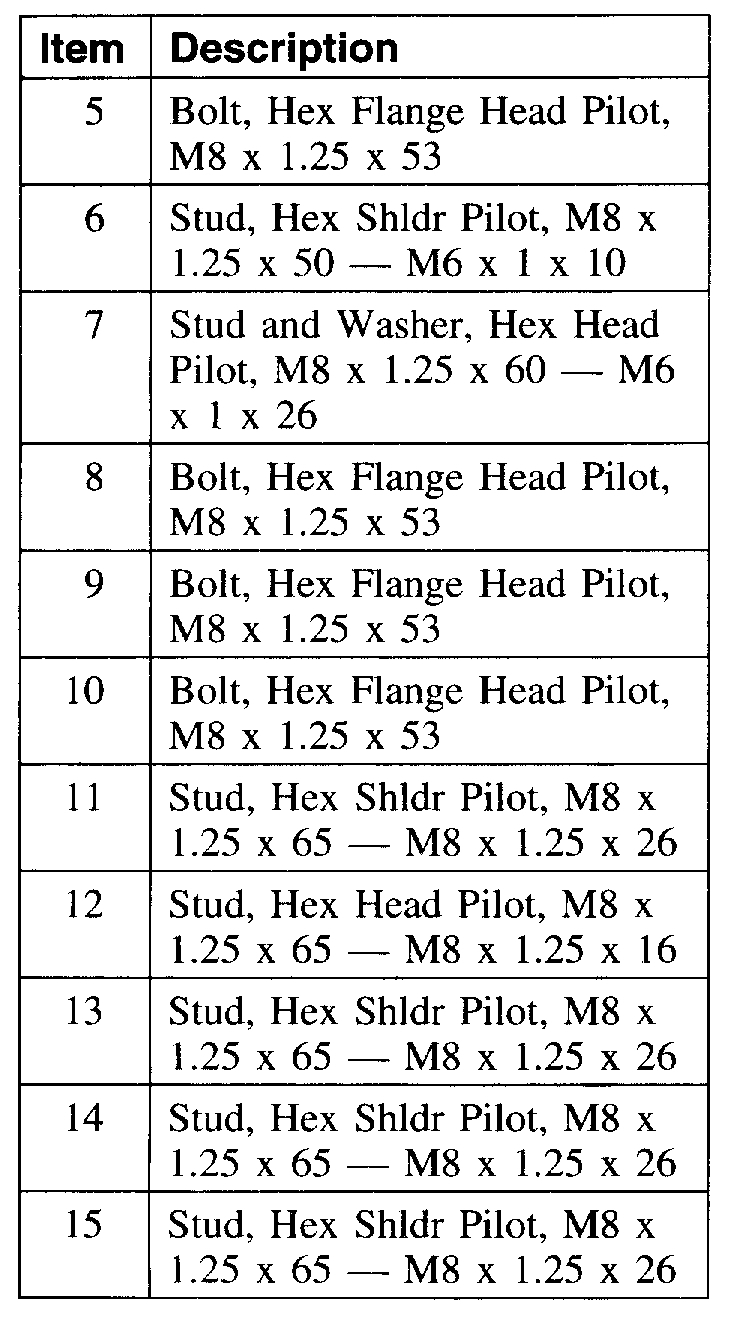
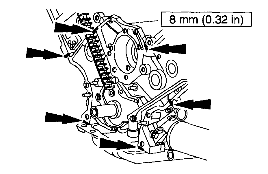
2. Remove the engine front cover fasteners in the sequence shown.
Item 24; Engine Front Cover Removal Note
1. Remove the transmission cooler line bracket from the stud.
2. Remove the engine front cover fasteners in the sequence shown.
Items 39 - 26: Crankshaft Gear Installation Note
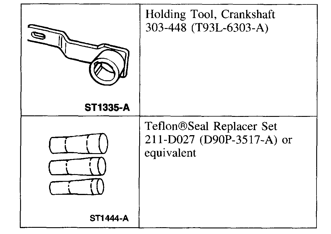
1. CAUTION: Rotate the crankshaft counterclockwise only. Do not rotate past the position shown or severe piston and/or valve damage will occur.
Using the special tool position the crankshaft.
^ Remove the special tool after crankshaft positioning.
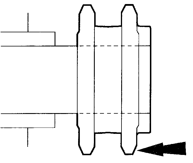
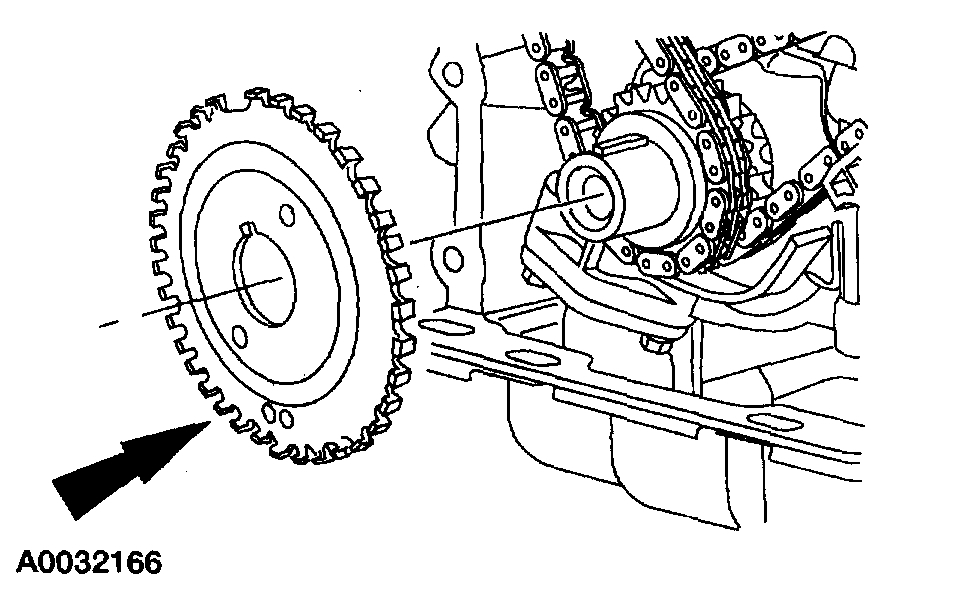
2. Install the crankshaft sprocket with the flange facing forward.
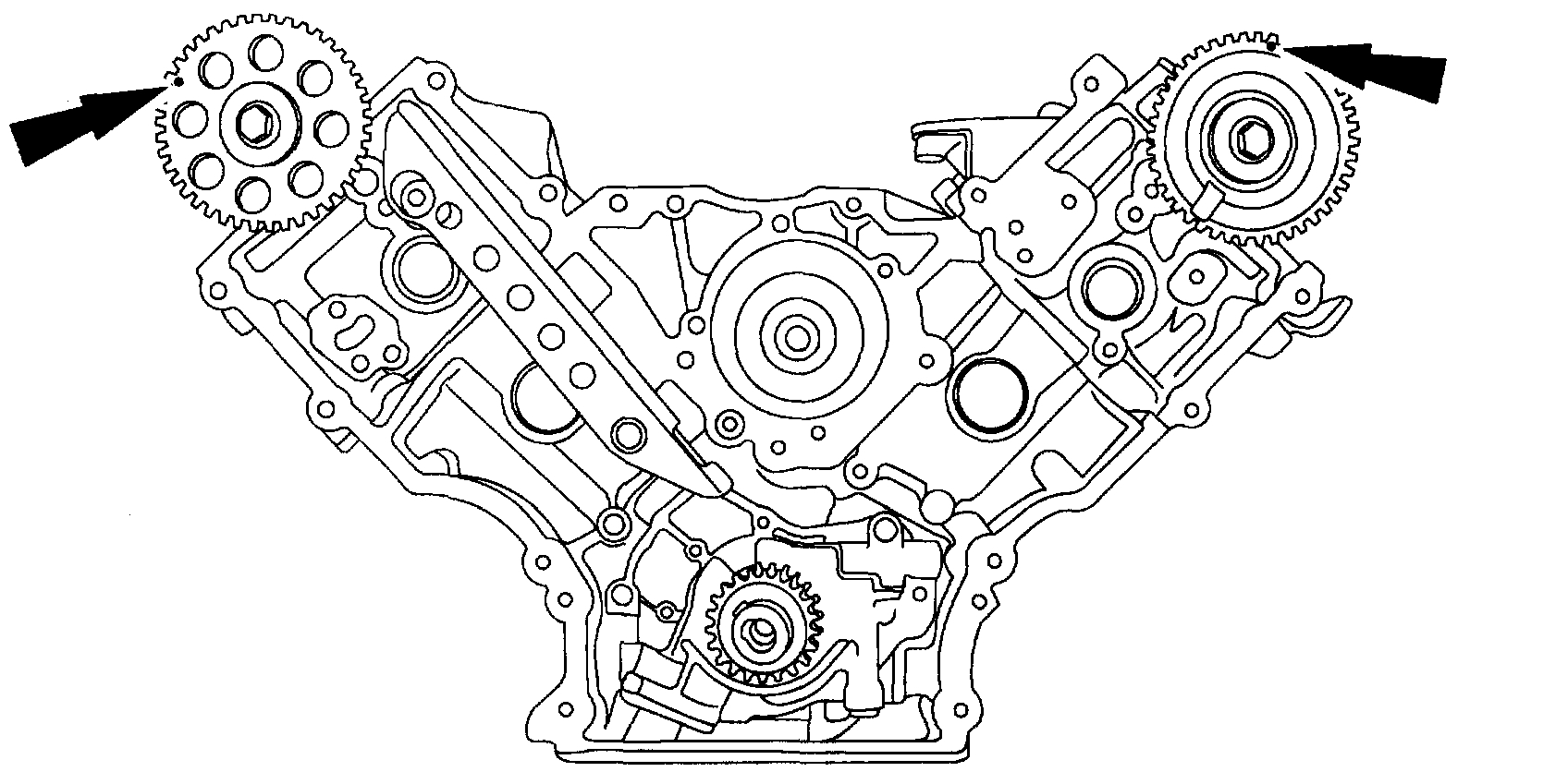
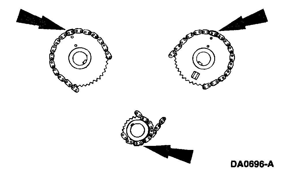
3. Rotate the LH camshaft timing sprocket until the timing mark is approximately at the 12 o'clock position. Rotate the RH camshaft timing sprocket until the timing mark is at approximately the 11 o'clock position.
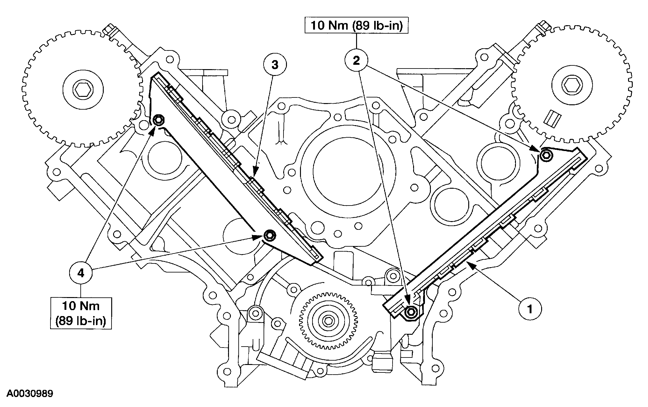
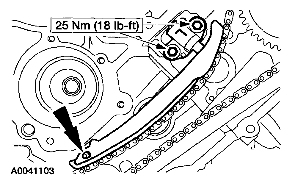
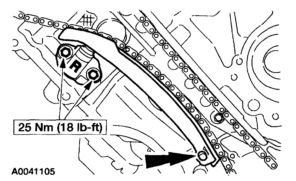
4. Install the timing chain guides.
1 Position the LH timing chain guide.
2 Install and tighten the LH bolts.
3 Position the RH timing chain guide.
4 Install and tighten the RH bolts.
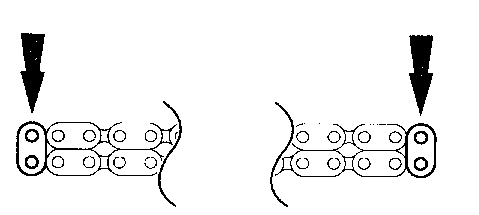
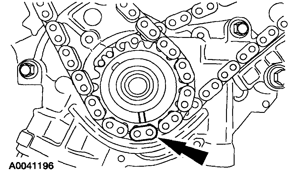
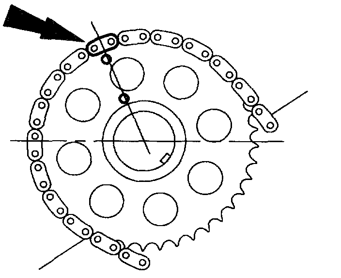
5. If the copper links are not visible, mark one link on one end and one link on the other end, and use as timing marks.
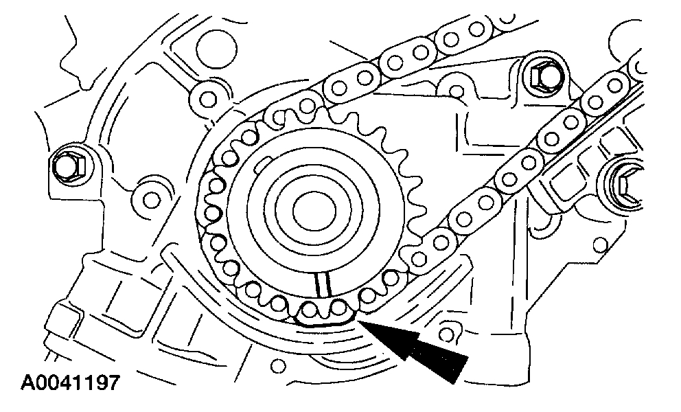
6. Position the LH (inner) timing chain on the crankshaft sprocket, aligning the copper (marked) link with the timing mark on the sprocket.
7. NOTE: If necessary, adjust the camshaft sprocket slightly to obtain timing mark alignment.
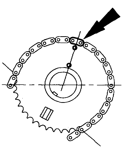
Position the LH timing chain on the camshaft sprocket. Make sure the copper - colored link aligns with the camshaft sprocket timing mark.
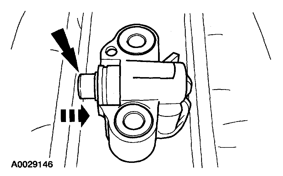
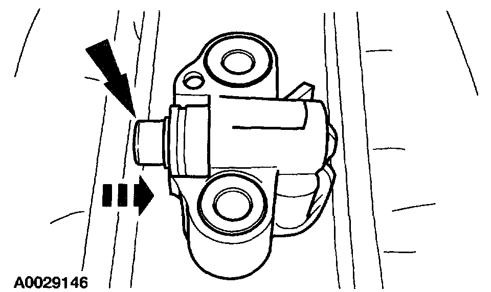
8. Compress the LH tensioner plunger, using a vise.
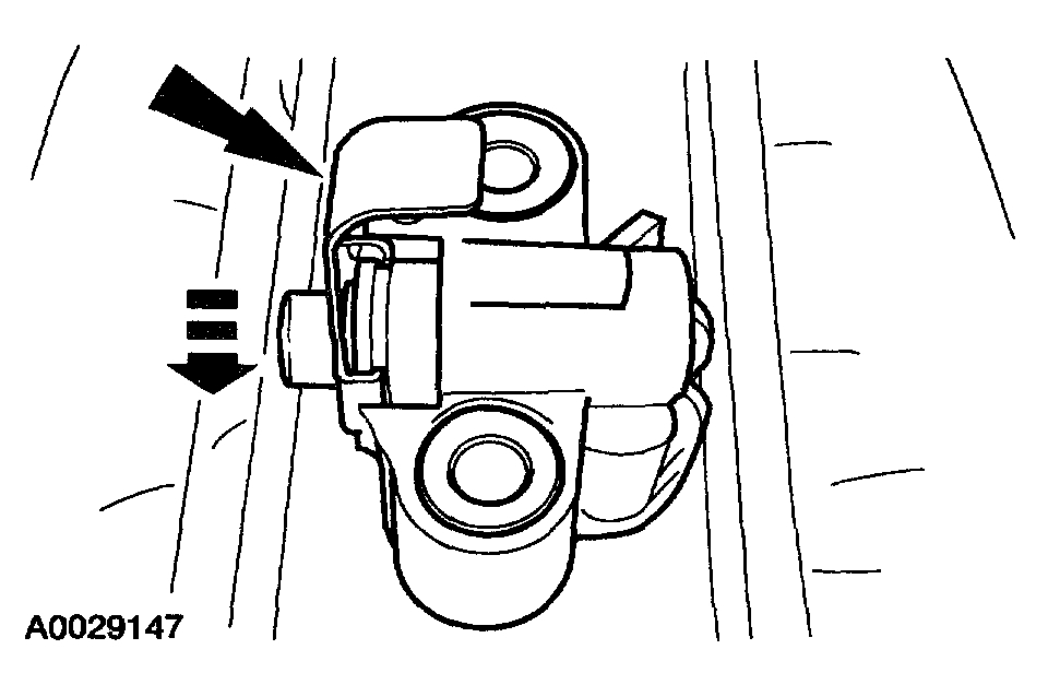
9. Install a retaining clip on the LH tensioner to hold the plunger in during installation.
10. NOTE: The LH timing chain tensioner arm has a bump near the dowel hole for identification.
Position the LH timing chain tensioner arm on the dowel pin and install the LH timing chain tensioner.
11. Remove the retaining clip from the LH timing chain tensioner.
12. Position the RH (outer) timing chain on the crankshaft sprocket, aligning the copper (marked) link with the timing mark on the sprocket.
13. NOTE: If necessary, adjust the camshaft sprocket slightly to obtain timing mark alignment.
Position the RH timing chain on the camshaft sprocket. Make sure the copper - colored link aligns with the camshaft sprocket timing mark.
14. Compress the RH tensioner plunger, using a vise.
15. Install a retaining clip on the RH tensioner to hold the plunger in during installation.
16. NOTE: The RH timing chain tensioner arm has a bump near the dowel hole for identification.
Position the RH timing chain tensioner arm on the dowel pin and install the RH timing chain tensioner.
17. Remove the retaining clip from the RH timing chain tensioner.
18. As a post - check, verify correct alignment of all timing marks.
19. Install the crankshaft sensor ring on the crankshaft.
Item 24: Engine Front Cover Installation Note
1. NOTE: If the engine front cover is not secured within four minutes, the sealant must be removed and the sealing area cleaned with metal surface cleaner. Allow to dry until there is no sign of wetness, or four minutes, whichever is longer. Failure to follow this procedure can result in future oil leakage.
Apply silicone gasket and sealant in the locations shown.
2. Install the engine front cover.
3. Tighten the four oil pan bolts in the sequence shown:
^ Stage 1: Tighten to 2 Nm (18 inch lbs.).
^ Stage 2: Tighten to 20 Nm (15 ft. lbs.).
^ Stage 3: Tighten an additional 60 degrees.
Item 2: Power Steering Pressure Hose Installation Note
1. Using the appropriate special tool, install a new O - ring seal on the power steering pressure hose fitting.
Item 1: Power Steering Pump Pulley Installation Note
1. Using the special tool, install the power steering pump pulley.
Check out the diagrams (Below). Please let us know if you need anything else to get the problem fixed.
Images (Click to enlarge)
Sep 10, 2019 at 8:01 PM