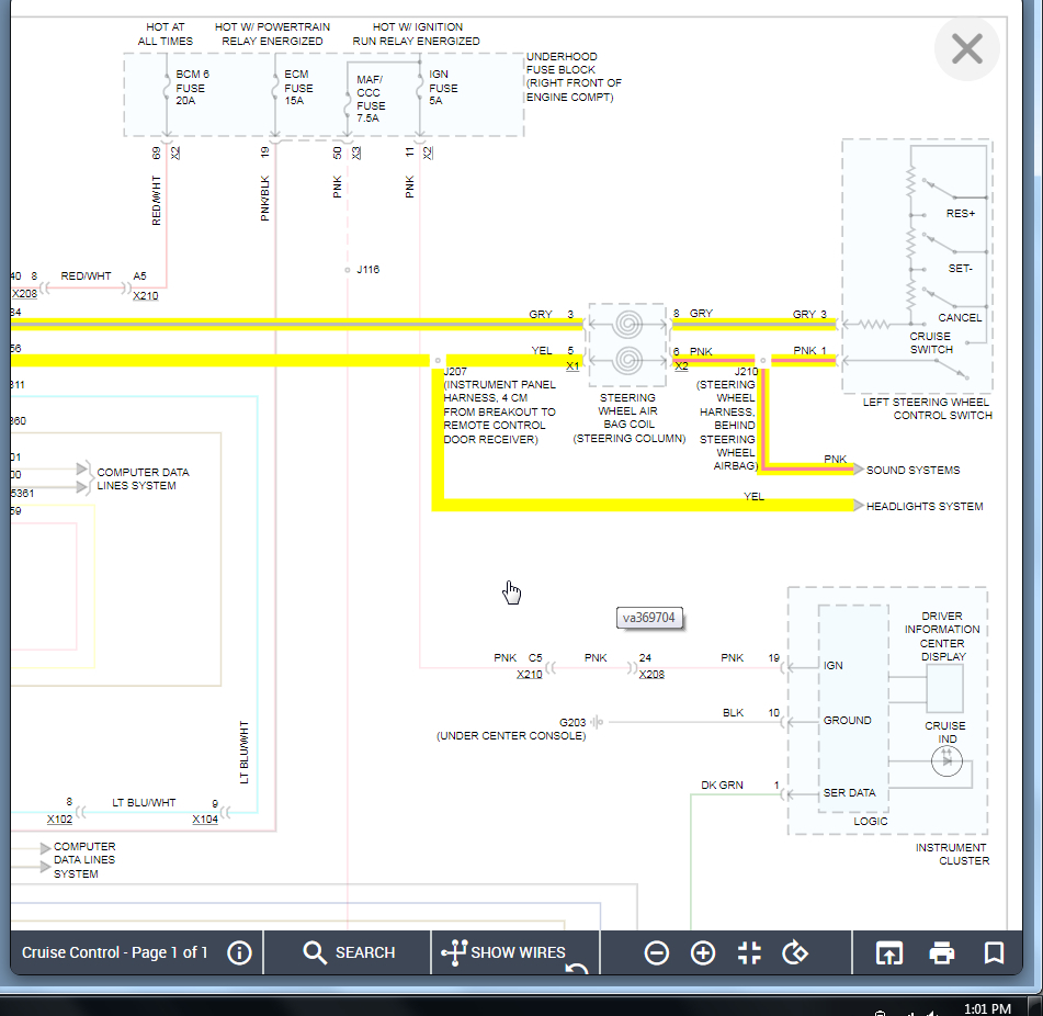
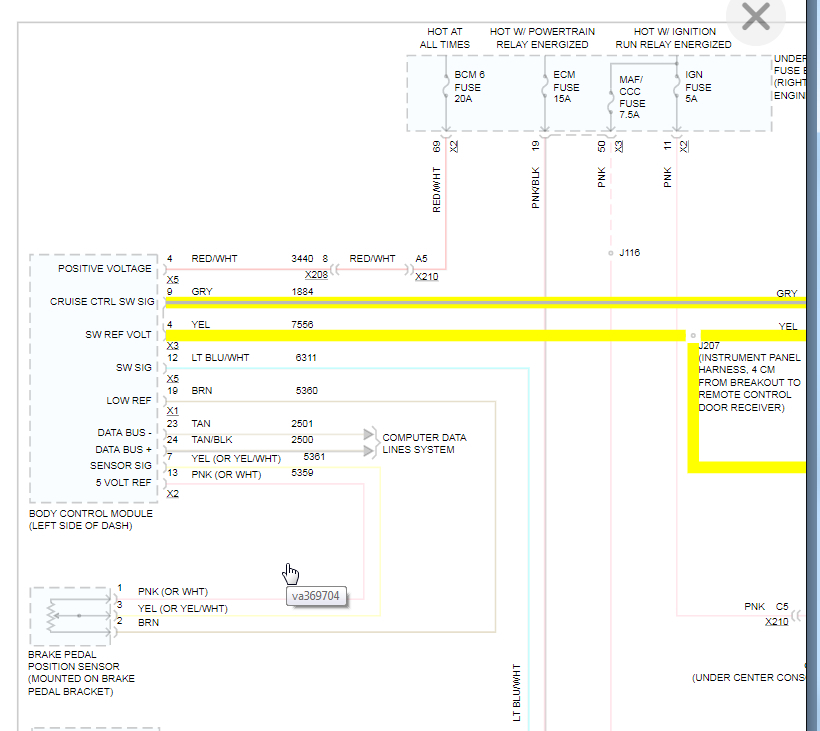
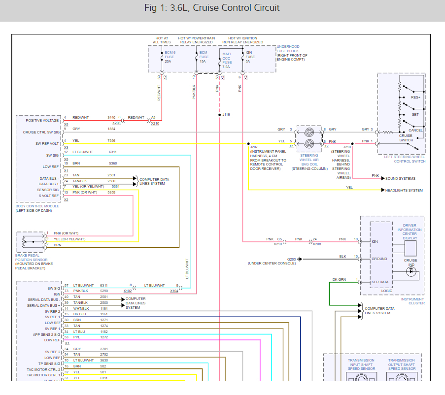
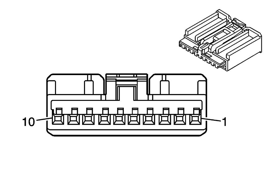
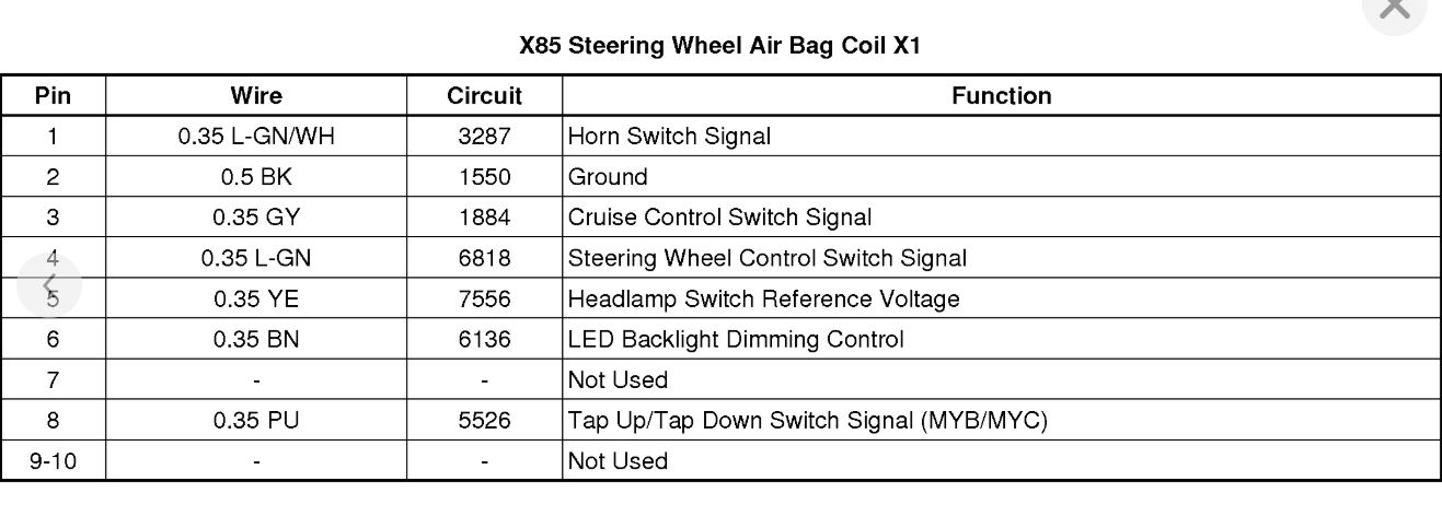
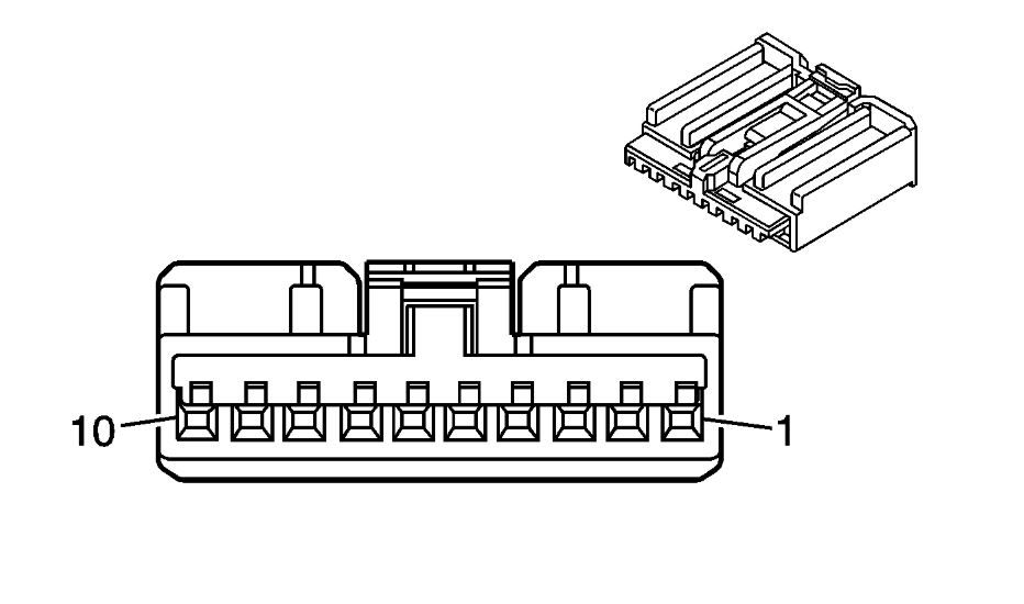
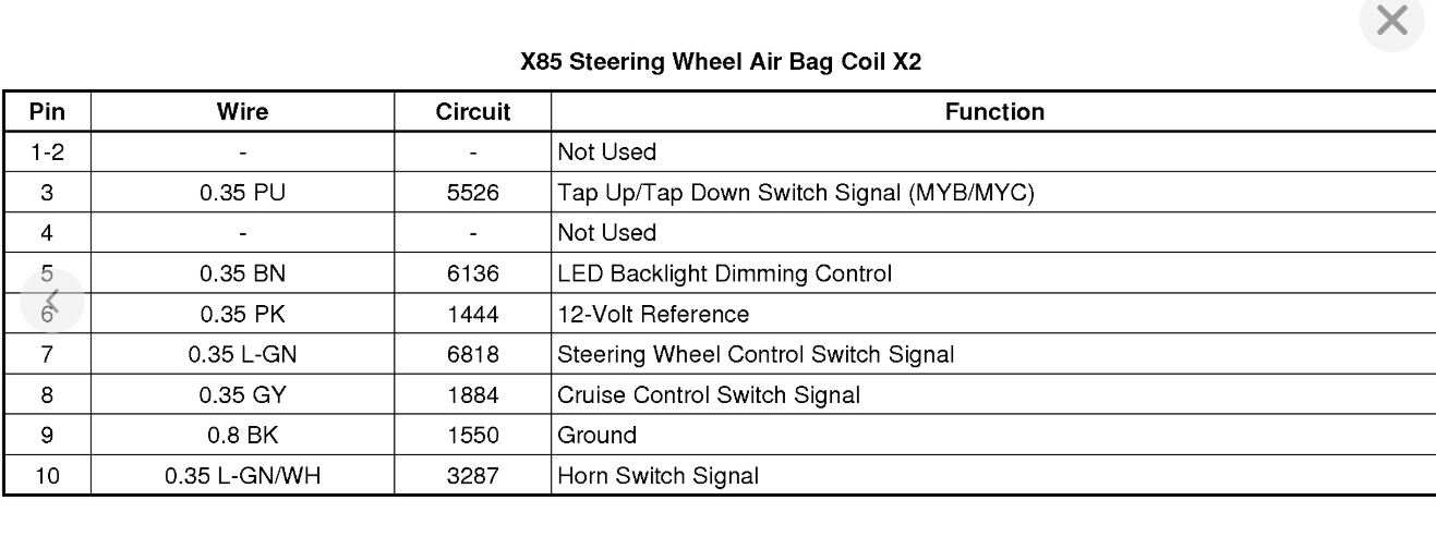
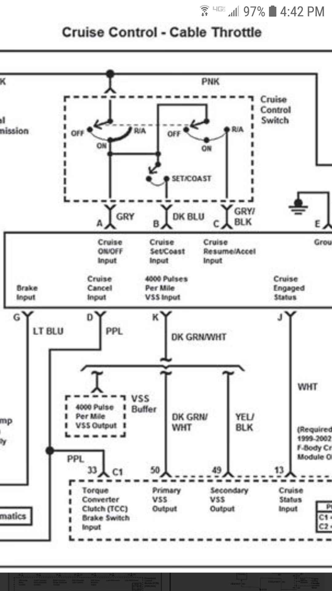
I think the issue is you saw a video on a different vehicle. Is that correct? If so, I suspect the confusion is coming in that the system in that vehicle was wired differently then your vehicle. If you take a look at these wiring diagrams, you are not able to find any wire for RES/SET/Cancel except the cruise signal wire because that is the only wire that is used. You don't have 3 separate wires that when the button is pressed it sends a signal to the BCM. You have a signal wire that the BCM will read the voltage on this single wire and depending on what it is, it knows what button is being pressed.
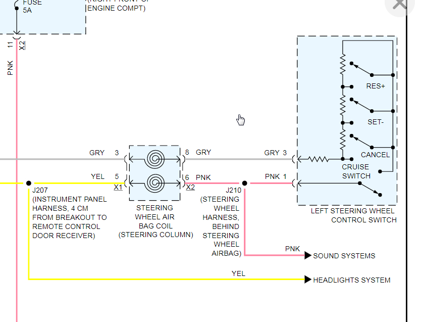
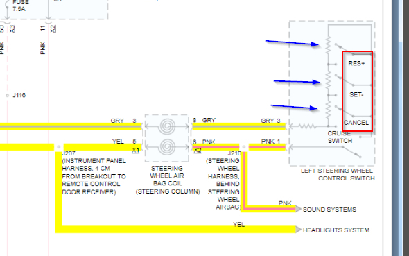
If you look at what the blue arrows I added are pointing too, those are resistors in the switch. This tells us that when the cancel button is pressed it grounds the signal wire and then BCM sees a voltage signal. When one of the other buttons are pressed, it grounds the signal wire but the voltage passes through other resistors and it changes the voltage the BCM sees so it knows that a different button has been pressed.
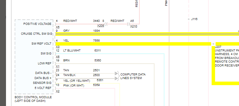
I imagine we can trick the BCM into thinking that your buttons are the stock buttons, we just need to know what the voltage is on the signal wire at the BCM when each button is pressed. Then you tap all three of your new buttons into this signal wire but you will need to add your own resistors to each wire so that when you press your new button it gives the same voltage to the BCM so it knows what button that is supposed to be.
Hopefully that makes sense. It is not the easiest thing because I don't know what the starting voltage is (I suspect it is 5 volts) to know what size resistors you need for each button in order to cut the voltage down to match the stock buttons.
First thing to do is monitor the voltage on that wire at the BCM and press each button to find out starting voltage and then how each button effects it.
Images (Click to enlarge)
Jun 23, 2020 at 8:17 PM