This sounds like you have one of two problems. first, I would check the battery because a weak battery can cause these problems. Here is a guide to show you how to do that:
https://www.2carpros.com/articles/car-battery-load-test
and if it tests bad
https://www.2carpros.com/articles/how-to-replace-a-car-battery
If the battery checks out then the electronic steering sounds like it needs replacing. Here are the instructions for that so you can see what needs to be done. Start with the battery disconnected.
Removal:
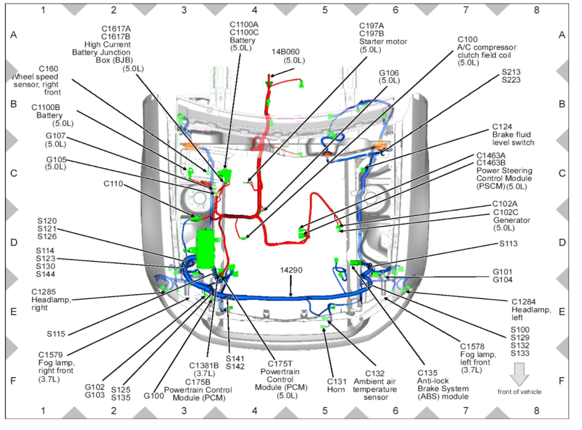
If installing a new steering gear, connect the scan tool and upload the module configuration information from the Power Steering Control Module (PSCM). For additional information, refer to Module Configuration See: Powertrain ManagementComputers and Control SystemsInformation BusTesting and InspectionProgramming and RelearningProgrammable Module Installation (PMI).
Disconnect the battery ground cable. For additional information, refer to Battery, Mounting and Cables See: Starting and ChargingBatteryBattery CableService and Repair.
Vehicles with 5.4L (4V) engine
Remove the battery and battery tray. For additional information, refer to Battery and Battery Tray-Exploded View in Battery, Mounting and Cables See: Starting and ChargingBatteryService and RepairBattery and Battery Tray - Exploded View. Remove the Air Cleaner (ACL) outlet pipe. For additional information, refer to Intake Air Systems Components-Exploded View, 5.4L (4V) in Intake Air Distribution and Filtering See: Powertrain ManagementFuel Delivery and Air InductionIntake Air DuctDiagrams.
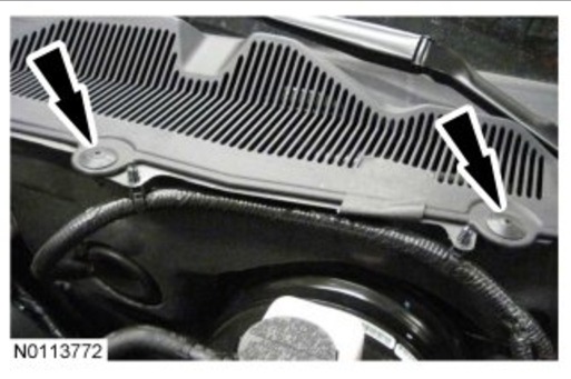
Remove the 2 LH cowl vent screen plastic rivets.
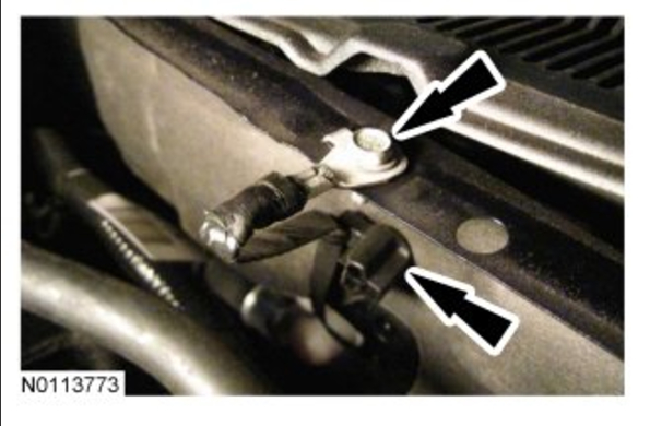
Lift the cowl screen and remove the ground strap bolt.
Detach the ground strap retainer from the cowl.
Disconnect the brake booster vacuum hose quick connect at the engine.
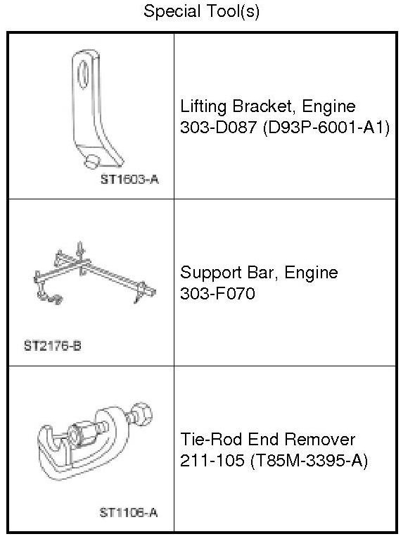
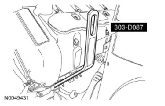
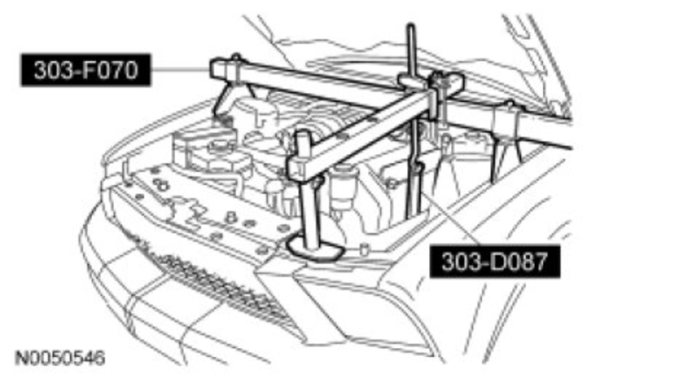
Install the Engine Lifting Bracket.
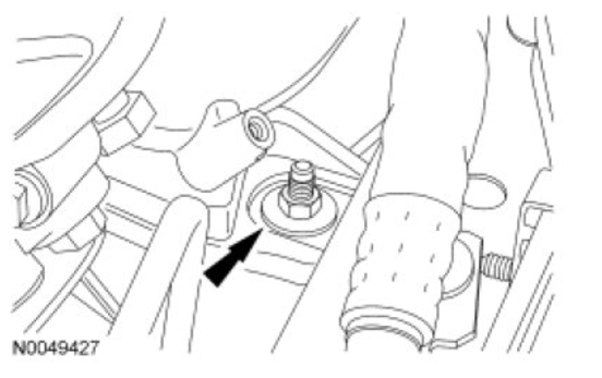
Remove the LH engine mount nut.
NOTICE: Lift engine approximately 45 mm (1.771 in) from the bottom of the engine mount to the bottom of the engine bracket ensuring that no contact is made with the bulk head or damage to components may occur.
Install the Engine Support Bar.
Using the Engine Lifting Bracket and Engine Support Bar, raise the LH side of the engine to gain clearance for removal of the LH steering gear mounting bolt.
With the vehicle in NEUTRAL, position it on a hoist. For additional information, refer to Jacking and Lifting See: Wheels and TiresVehicle LiftingService and Repair.
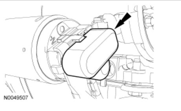
Remove the starter solenoid terminal cover.
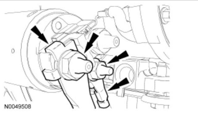
Remove the 2 nuts and disconnect the 2 wires from the starter solenoid.
Position the wheels to gain access to the steering column shaft coupling-to-steering gear bolt.
NOTICE: Do not allow the steering column to rotate while the steering column shaft is disconnected from the steering gear or damage to the clockspring may occur. If there is evidence that the steering column has rotated, the clockspring must be removed and recentered. For additional information, refer to Supplemental Restraint System See: Restraints and Safety SystemsAir Bag SystemsClockspring Assembly / Spiral CableService and Repair.
Remove the steering column shaft coupling-to-steering gear bolt.
Discard the bolt.
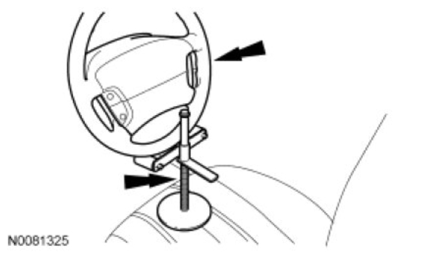
NOTE: Use a steering wheel holding device (such as Hunter(R) 28-75-1 or equivalent).
Using a suitable holding device, hold the steering wheel in the straight-ahead position.
NOTE: The steering column shaft coupling will not be completely separated from the steering gear.
Slide the steering column shaft coupling upwards on the steering gear input shaft.
Remove the wheels and tires. For additional information, refer to Wheels and Tires See: Wheels and TiresService and RepairRemoval and Replacement.
Remove and discard the 2 tie-rod end nuts.
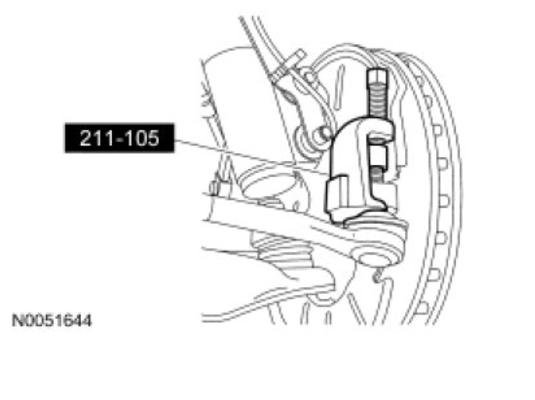
NOTICE: Do not use a hammer to separate the outer tie-rod end from the wheel knuckle or damage to the wheel knuckle may result.
Using the Ball Joint Separator, separate the tie-rod ends from the wheel knuckles.
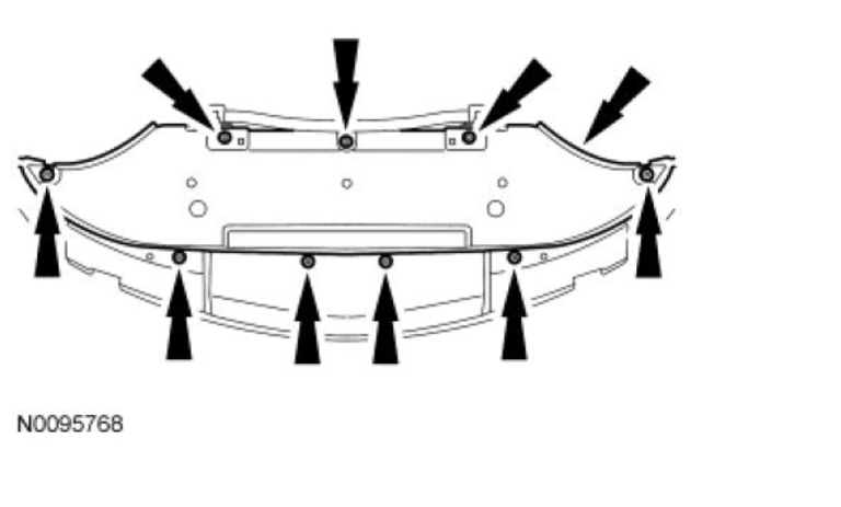
Remove the 9 screws and the lower splash shield.
If equipped, loosen the 2 cross member brace nuts.
If equipped, remove the 6 cross member brace bolts and the cross member brace.
Vehicles with automatic transmission
Remove the 2 transmission cooler line bracket nuts and position tubes aside.
All vehicles
Remove the 4 rearward subframe crossmember brace nuts and crossmember brace.
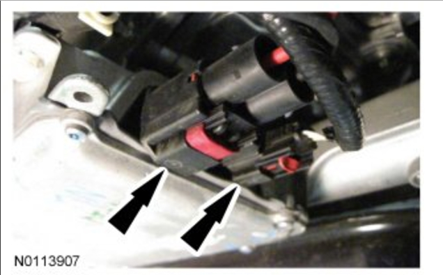
NOTICE: The ignition must be off when disconnecting Electronic Power Assist Steering (EPAS) electrical connectors. Failure to follow this direction may lead to DTCs being set in the EPAS module that can not be cleared, and result in the need to install a new EPAS assembly.
Release the 2 red Connector Position Assurance (CPA) features and disconnect the 2 Electronic Power Assist Steering (EPAS) electrical connectors.
Detach the wiring harness pin-type retainers.
NOTE: If equipped with a 5.4L (4V) engine, it may be necessary to use a pry bar between the LH engine mount and engine bracket, pulling the engine forward slightly to remove LH steering gear bolt
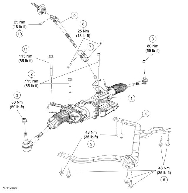
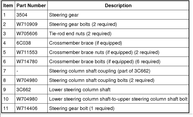
Remove the 3 steering gear bolts and the steering gear.
Discard the bolts.
Installation
All vehicles
NOTICE: Do not allow the steering column to rotate while the steering column shaft is disconnected from the steering gear or damage to the clockspring may occur. If there is evidence that the steering column has rotated, the clockspring must be removed and recentered. For additional information, refer to Supplemental Restraint System See: Restraints and Safety SystemsAir Bag SystemsClockspring Assembly / Spiral CableService and Repair.
NOTE: Make sure the steering column coupling is aligned with the locator on the steering gear input shaft and the shaft is fully seated on the steering gear.
Position the steering gear, attach the steering column coupling and install the 3 steering gear bolts.
Tighten to 115 Nm (85 lb-ft).
NOTE: Make sure the Electronic Power Assist Steering (EPAS) electrical connectors are fully seated and the Connector Position Assurance (CPA) features are engaged.
Connect the 2 Electronic Power Assist Steering (EPAS) electrical connectors and secure the 2 red Connector Position Assurance (CPA) features.
Attach the wiring harness pin-type retainers.
Vehicles with automatic transmission
Position the transmission cooler tube brackets and install the 2 nuts.
Tighten the cooler tube bracket-to-transmission nut to 12 Nm (106 lb-in).
Tighten the cooler tube bracket-to-engine mount nut to 48 Nm (35 lb-in).
All vehicles
Position the rearward subframe crossmember brace and install the 4 nuts.
Tighten to 48 Nm (35 lb-ft).
If equipped, position the crossmember brace and install the 6 bolts.
Tighten to 48 Nm (35 lb-ft).
If equipped, tighten the 2 crossmember brace nuts to 48 Nm (35 lb-ft).
Position the lower splash shield and install the 9 screws.
Position the 2 tie-rod ends and install the 2 new tie-rod end nuts.
Tighten to 80 Nm (59 lb-ft).
Install the wheels and tires. For additional information, refer to Wheels and Tires See: Wheels and TiresService and RepairRemoval and Replacement.
Position the steering wheel approximately 120 degrees to the left to access to the steering column coupling bolt hole and install the steering column coupling-to-steering gear bolt.
Tighten to 25 Nm (18 lb-ft).
Connect the 2 wires and install the 2 nuts on the starter solenoid.
Tighten the B+ terminal to 12 Nm (106 lb-in).
Tighten the S-terminal to 5 Nm (44 lb-in).
Install the starter solenoid terminal cover.
Vehicles with 5.4L (4V) engine
NOTE: While lowering the engine, make sure that the engine bracket aligns to the engine mount stud bolt. If necessary, shift the engine slightly when lowering.
Using the Engine Lifting Bracket and Engine Support Bar, lower the LH side of the engine onto the engine mount.
Install the LH engine mount nut.
Tighten to 63 Nm (46 lb-ft).
Connect the brake booster vacuum hose quick connect.
Install the ground strap bolt and attach the retainer.
Tighten to 6 Nm (53 lb-in).
Install the 2 cowl vent screen plastic rivets.
Install the Air Cleaner (ACL) outlet pipe. For additional information, refer to Intake Air Systems Components-Exploded View, 5.4L (4V) in Intake Air Distribution and Filtering See: Powertrain ManagementFuel Delivery and Air InductionIntake Air DuctDiagrams.
Install the battery and battery tray. For additional information, refer to Battery, Mounting and Cables See: Starting and ChargingBatteryService and RepairBattery and Battery Tray - Exploded View.
All vehicles
Connect the battery ground cable. For additional information, refer to Battery, Mounting and Cables See: Starting and ChargingBatteryBattery CableService and Repair.
When installing a new steering gear, it must be configured (using vehicle as-built data or module configuration information retrieved earlier in this procedure). For additional information on configuration, refer to Programmable Module Installation (PMI) in Module Configuration See: Powertrain ManagementComputers and Control SystemsInformation BusTesting and InspectionProgramming and RelearningProgrammable Module Installation (PMI).
Please let us know what happens so it will help others.
Cheers, Ken
Images (Click to enlarge)
Sep 12, 2017 at 11:56 AM