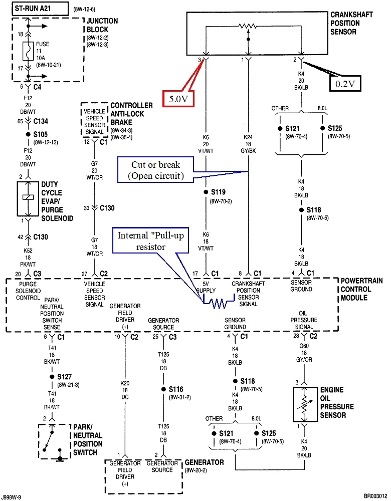
Where were you measuring that .97 and 1.3 volts? It sounds like that is on the sensor's ground wire. To clarify, in some service manuals the "low reference" terminology is used for a sensor's ground wire, while here in Chrysler's diagram they do call it a sensor ground. The difference has to do with the fact the black / light blue is the ground wire, but it doesn't actually go to ground. It travels through the Engine Computer first so it can be monitored. That circuit exits the computer on a different ground wire that usually IS called a ground wire. That leads us to the next point of value. That monitoring circuitry is what results in there being 0.2 volts on the sensor's ground wire, and not the 0.0 volts you'd expect. I just wanted to explain that to head off any potential confusion later. For our story, we can call it the "low reference" or the ground wire and mean the same thing. Also, sometimes you'll see "5 volt reference". That seems like a deliberate attempt at adding confusion, so I'll try to stick with "5-volt supply" and "ground".
It sounds like you're on the right track but may have not realized you found the clue. That's the 5.11 volts you found on the ground wire when the defect occurred. That can only occur if there's a break in the ground wire. That break can be where I drew the black callout at the black / light blue wire, the computer's ground wire, or the monitoring circuit inside the computer. Chrysler typically uses four ground wires on their Engine Computers. Two are called "power Grounds" for high-current circuits like injectors and ignition coils. The high current pulses going through them will cause small voltage drops that are insignificant to those systems, but they would mean a real lot to some sensors. That's why sensors get their own "signal ground" wires, and there's two of them for redundancy.
When there's a break in the ground circuit, 5.0 volts is going to appear on the other wires. You went one step further by cutting the signal wire. That is something we would never do. You'll accomplish the same thing by simply unplugging the sensor. When you do that with any three-wire sensor, there's no way to know what voltage you'll find on that signal wire on the computer side due to it being interconnected internally to all kinds of circuitry. It is possible for that voltage to "float" to some random value. As long as that voltage remains within the acceptable limits, the computer would accept it and try to run on it, even though it is wrong. To avoid that, all computer sensor signal circuits use either a "pull-down" or a "pull-up" resistor. Imports usually use pull-down resistors. Chrysler uses pull-up resistors most of the time. I drew one in this diagram in blue.
The important point of pull-up resistors is they are so huge electrically, in the order of hundreds of megohms, that they have absolutely no effect on anything as long as the circuit is working properly. It's when there' a break in that signal wire or inside the sensor that the pull-up resistor puts 5.0 volts onto the signal wire to force a defective condition to be detected. That is one way the computer determines when and which diagnostic fault code to set. This is why you're finding 5.11 volts on the signal wire.
So that signal wire can be explained away, but not so for the 5.11 volts on the ground wire. While not shown here, that black / light blue ground circuit is usually shared with a few other sensors, all of which would also stop working at the same time. The fact that you found your way to the crank sensor suggests you had a diagnostic fault code related to it. If that is correct, and there were no fault codes for other sensors, suggests the break in the ground has to be between the crank sensor, terminal # 2 and splice S125.
You do however have an additional symptom of hearing relays click intermittently. One thought points us to multiple circuits sharing a computer ground wire. Another thought is the break in the ground wire is healing itself enough that the crank sensor starts generating sporadic signals. Those signals are what tells the computer the engine is rotating, and that is when the computer turns on the automatic shutdown (ASD) relay to power up the injectors, ignition coils, and fuel pump relay. What this boils down to is we can't be sure where the break will be found in that ground circuit. Use this diagram to get started. I'm going to look for the computer's ground wires. I'll be back shortly with an update with those.
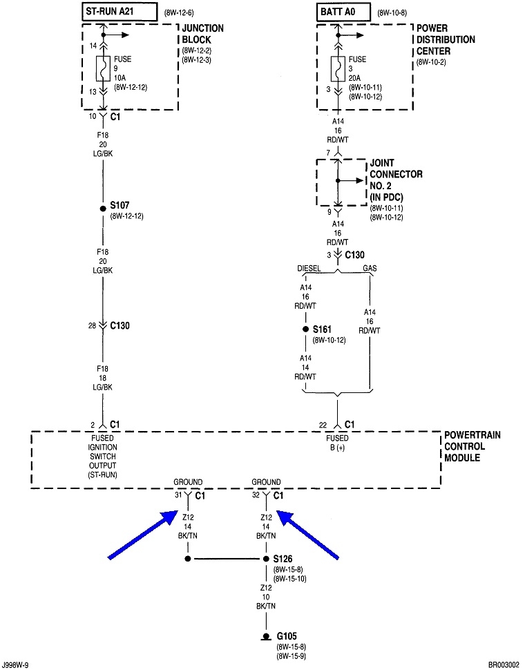
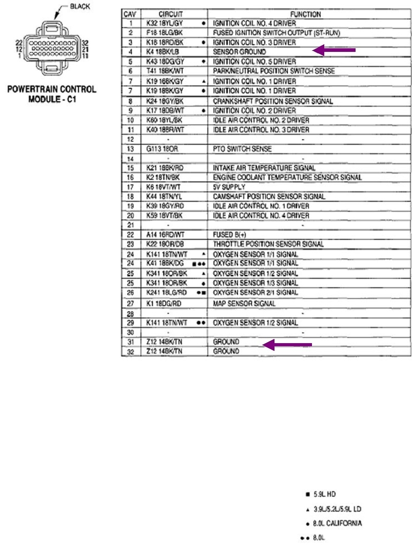
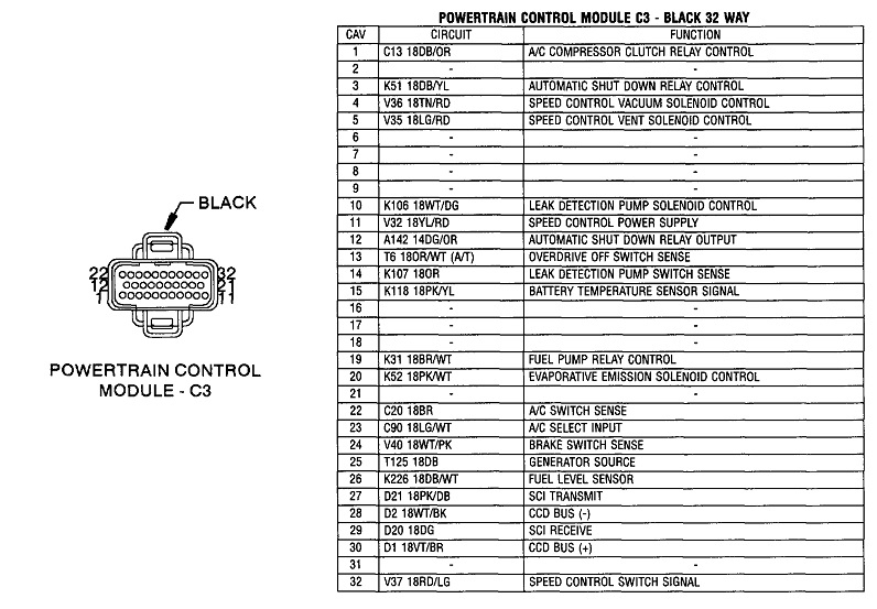
Update: I found two ground wires in connector C1, terminals 31 and 32. Unless I overlooked it, I don't see any separate "signal" wires. I added an arrow to terminal four, then realized it's for multiple sensors, not a computer ground as stated in the chart. It's possible splice S118 has another wire that goes to ground. That would make sense because then the oil pressure sensor's ground circuit wouldn't be monitored, and that's fine because it doesn't affect engine performance.
Regardless, the way you're checking this circuit with voltage readings is the best way to do it. Most people would try to use an ohm meter, but that is much less accurate. All you need is one tiny strand of wire to still be intact for an ohm meter to say the circuit is okay. You can't get enough current through just one strand, and that's where the voltage drop will show up as unacceptable, (more than 0.2 volts)
I made these drawing as large as I could. If you need me to, I can cut them in half, then blow them up larger, if it will help.
As a possible hint, you might want to watch the oil pressure gauge on the dash. If it drops before the engine stalls, a corroded splice S118 would be a good suspect, along with the ground wire that I think is there but not shown. If the intermittent break is up closer to the crank sensor, the oil gauge won't drop until right after the engine stalls.
Images (Click to enlarge)
Oct 2, 2022 at 6:59 PM