Hi,
The rule of thumb I learned years ago was 9.6v was a minimum while starting to allow it to start.
As far as the problem, I am attaching the diagnostics for a no spark condition. I have a feeling you have already done a lot of it. However, look through it and see if there is something you may have missed. The attached pics are the actual flow charts. If I'm reading them correctly, it could even be related to the cam sensor.
__________________________________
2003 GMC Truck C 1500 Truck 2WD V6-4.3L VIN W
Electronic Ignition (EI) System Diagnosis
Vehicle Powertrain Management Ignition System Testing and Inspection Component Tests and General Diagnostics Electronic Ignition (EI) System Diagnosis
ELECTRONIC IGNITION (EI) SYSTEM DIAGNOSIS
DISTRIBUTOR IGNITION (EI) SYSTEM DIAGNOSIS
SYSTEM DESCRIPTION
This system includes the crankshaft position (CKP) sensor, the camshaft position (CMP) sensor, the ignition coil with the ignition control (IC) module, the secondary wires, the spark plugs, and the circuit conductors and connectors.
The powertrain control module (PCM) controls the ignition system. The PCM monitors the input signals from various engine sensors. The PCM controls the dwell of the ignition primary coil, computes the desired spark timing and firing of the ignition system via an IC timing control circuit to the ignition control module.
The Distributor Ignition (DI) System Diagnostic Table assumes the following conditions:
- The battery is fully charged.
- There is adequate fuel in the fuel tank.
- The fuel delivery system is functional.
DIAGNOSTIC AIDS
Engine mechanical conditions may prevent the distributor from rotating. Inspect the following if the distributor rotor does not rotate:
- A broken distributor drive shaft
- A worn or broken distributor drive gear
- A worn or broken camshaft timing chain and gears
An intermittent may be caused by a poor connection, rubbed through wire insulation, or a wire broken inside the insulation. Refer to Testing for Intermittent and Poor Connections in Diagnostic Aids. If a repair is necessary, refer to Wiring Repairs in Diagnostic Aids.
TEST DESCRIPTION
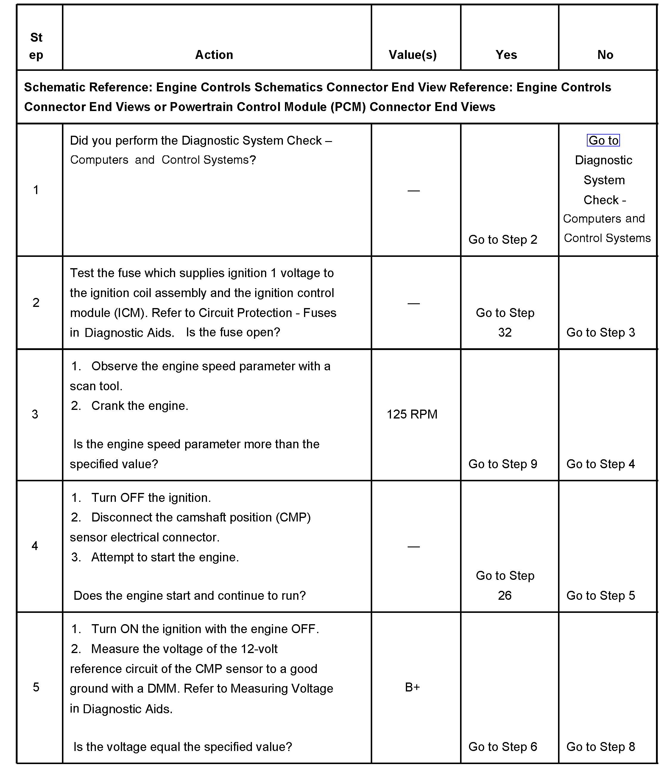
Steps 1-5
pic 1
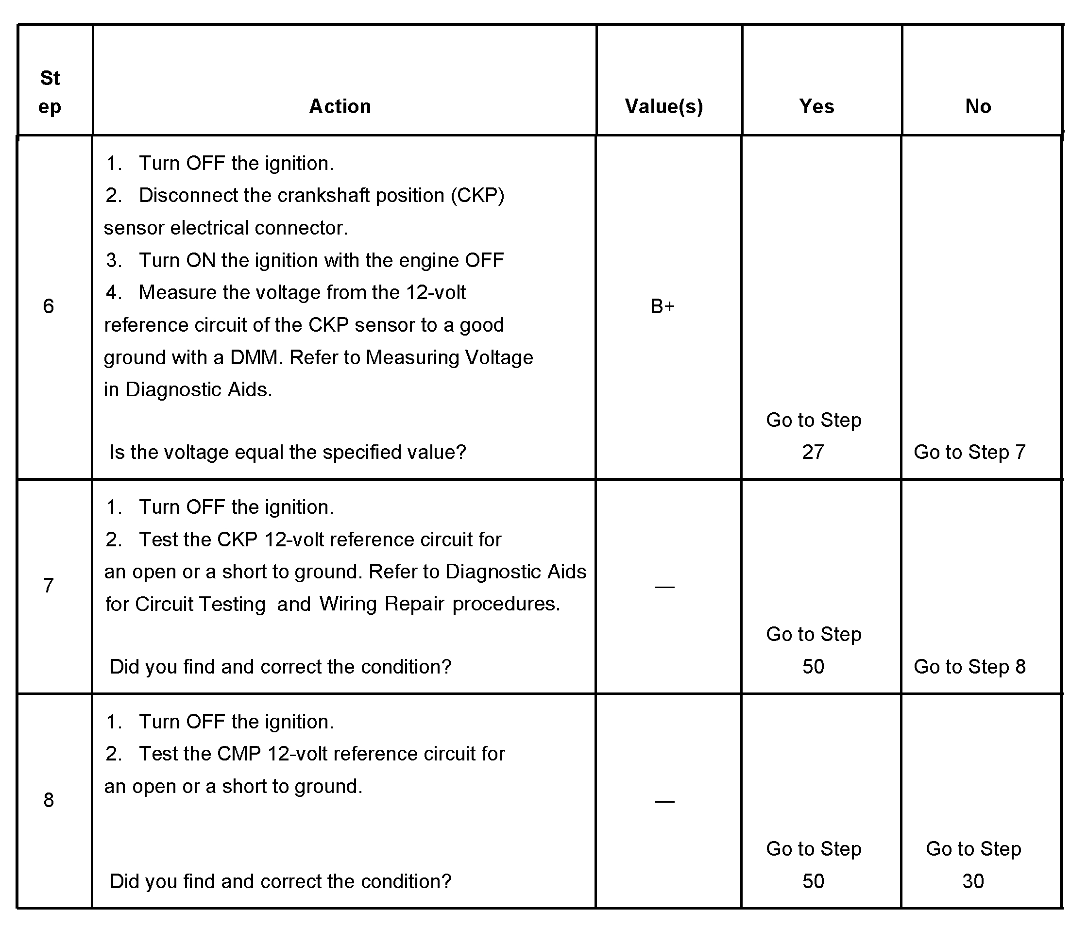
Steps 6-8
pic 2
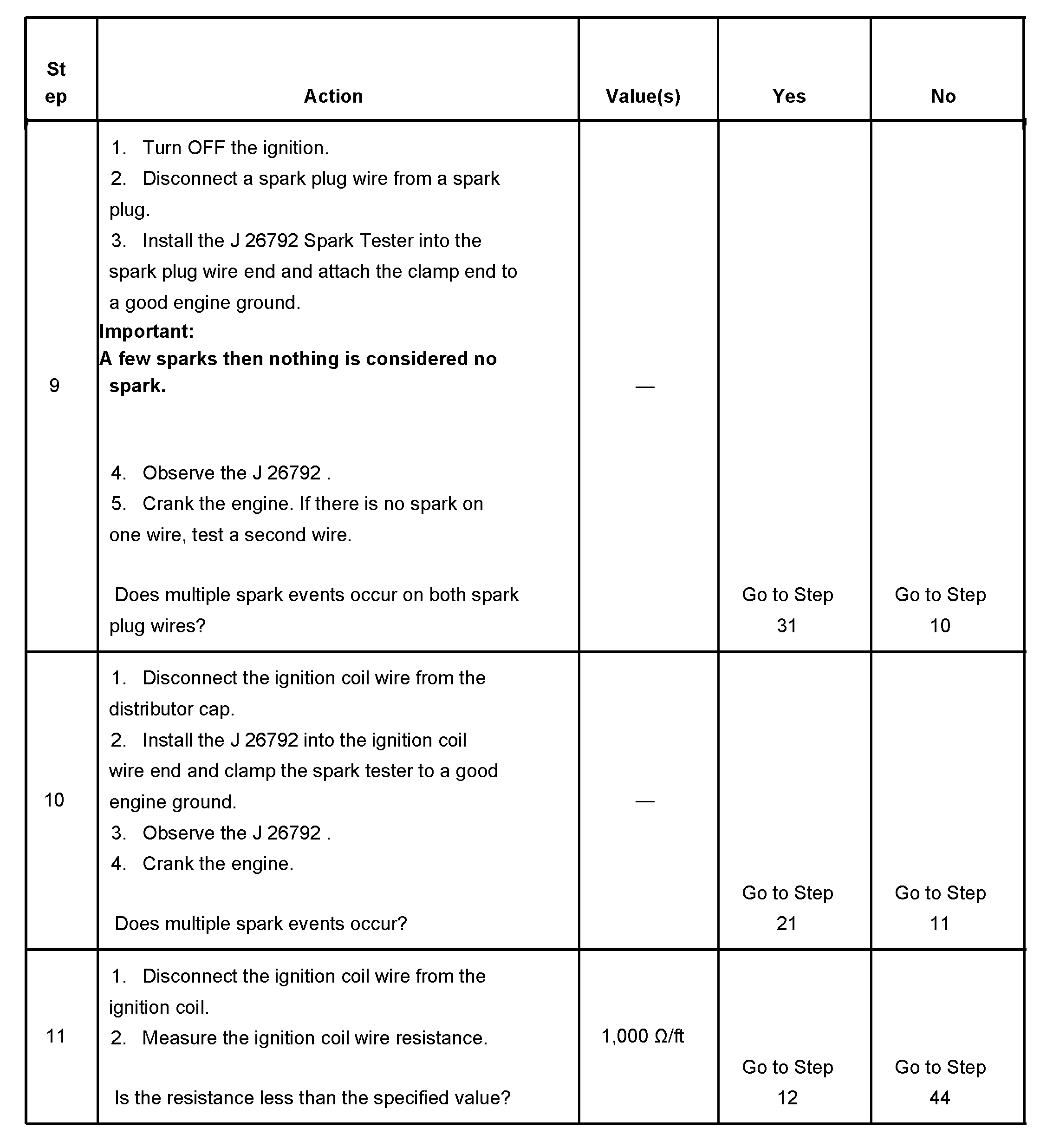
Steps 9-11
pic 3
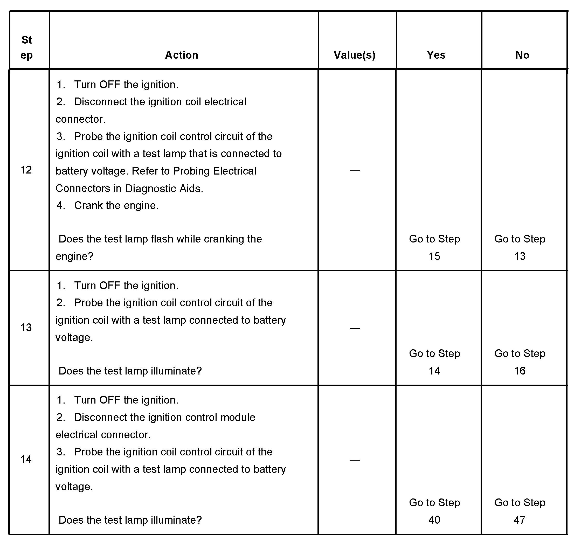
Steps 12-14
pic 4
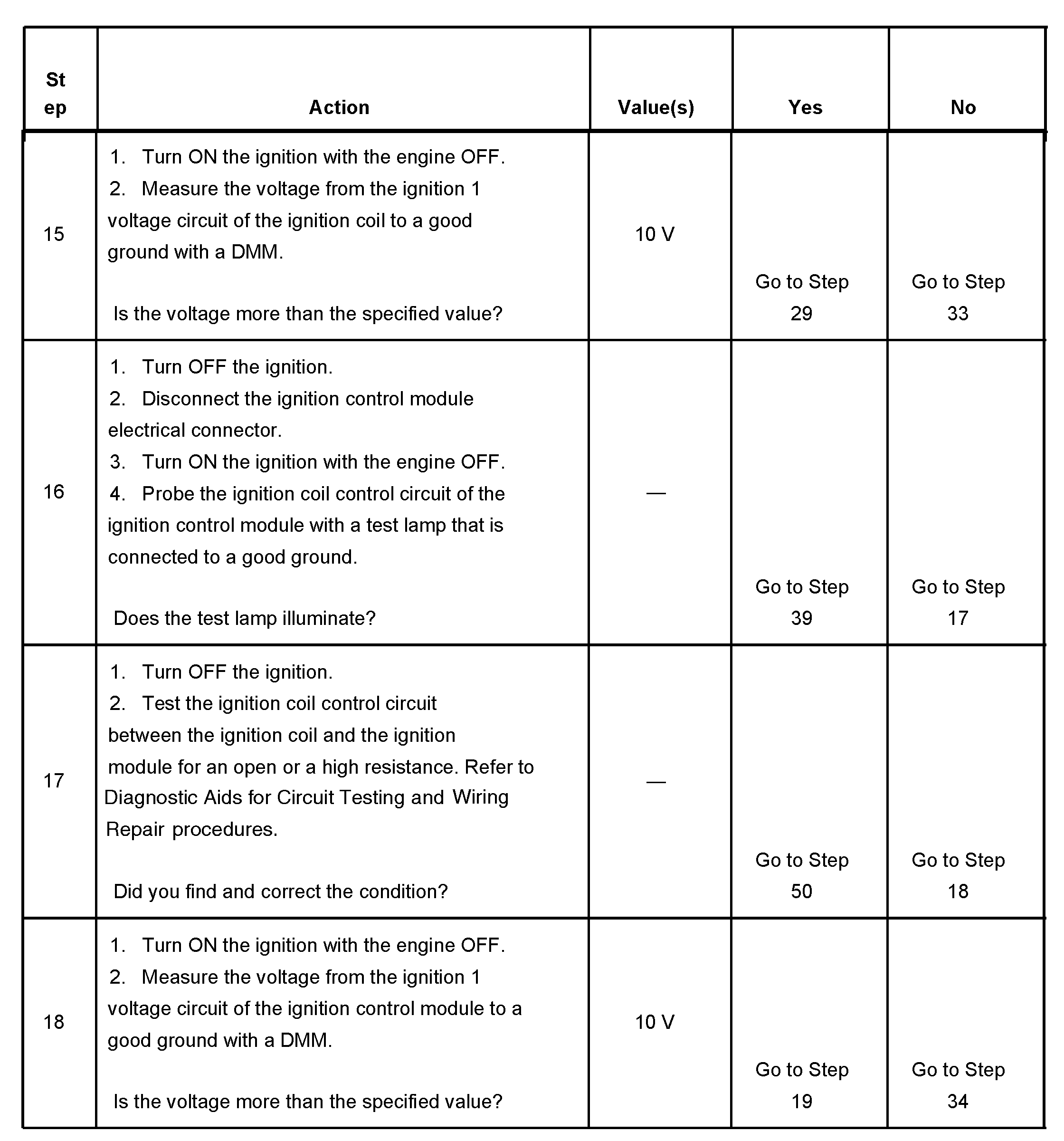
Steps 15-18
pic 5
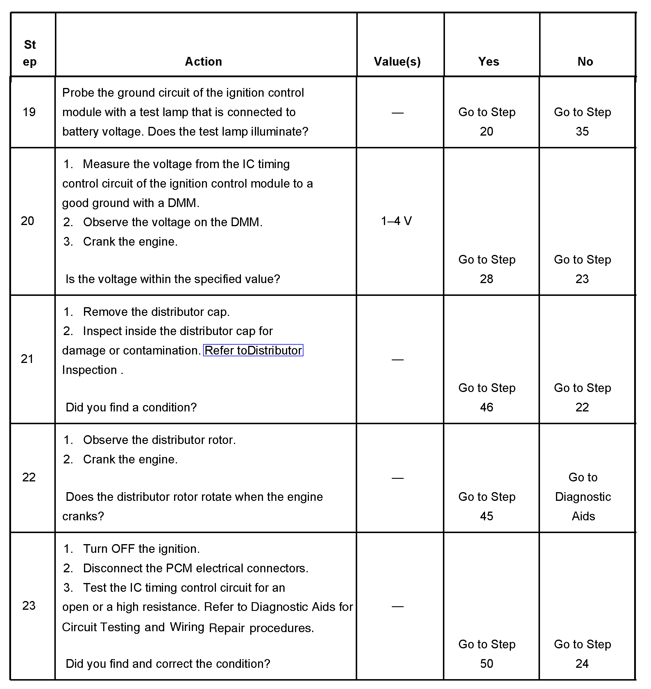
Steps 19-23
pic 6
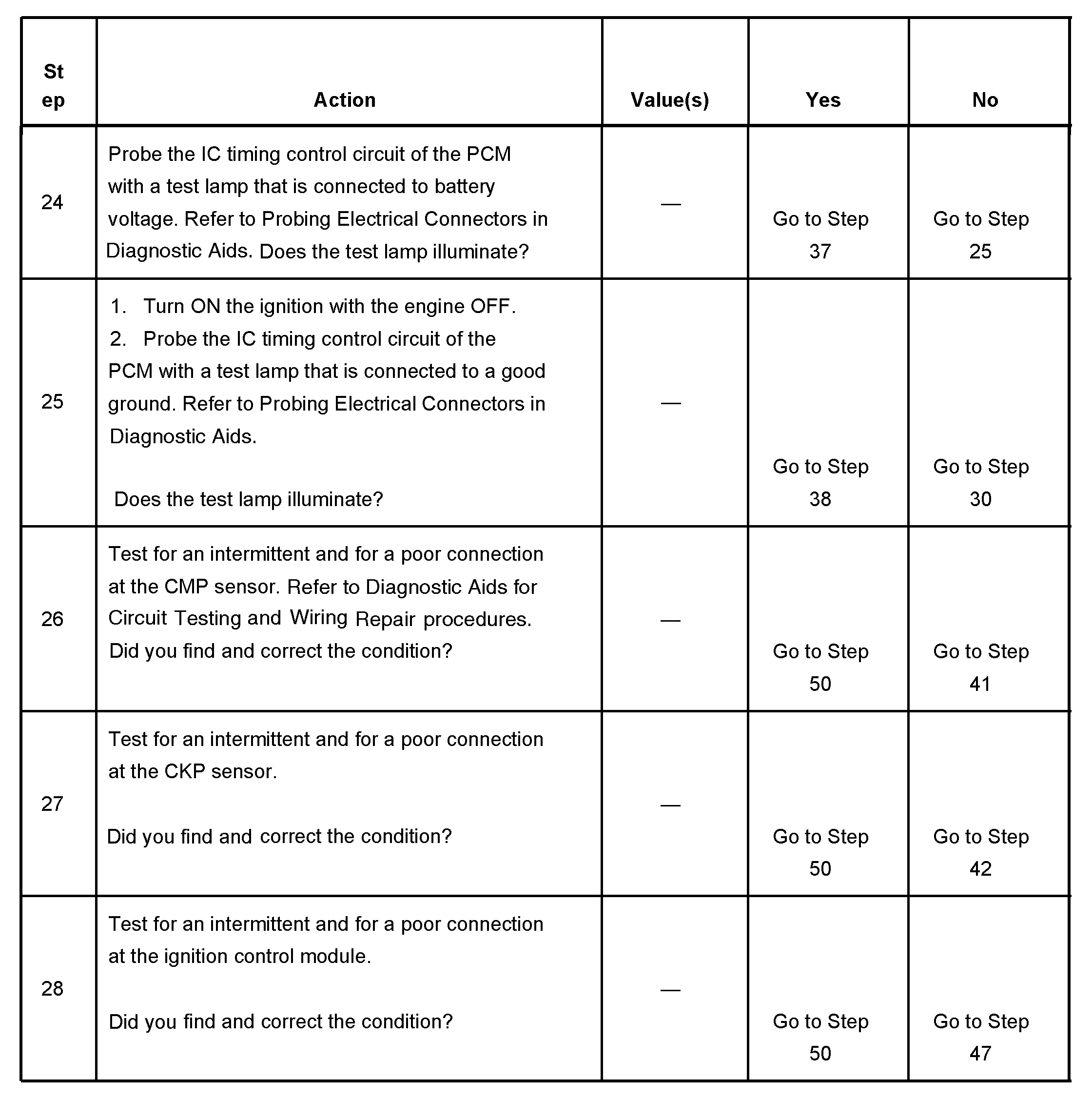
Steps 24-28
pic 7
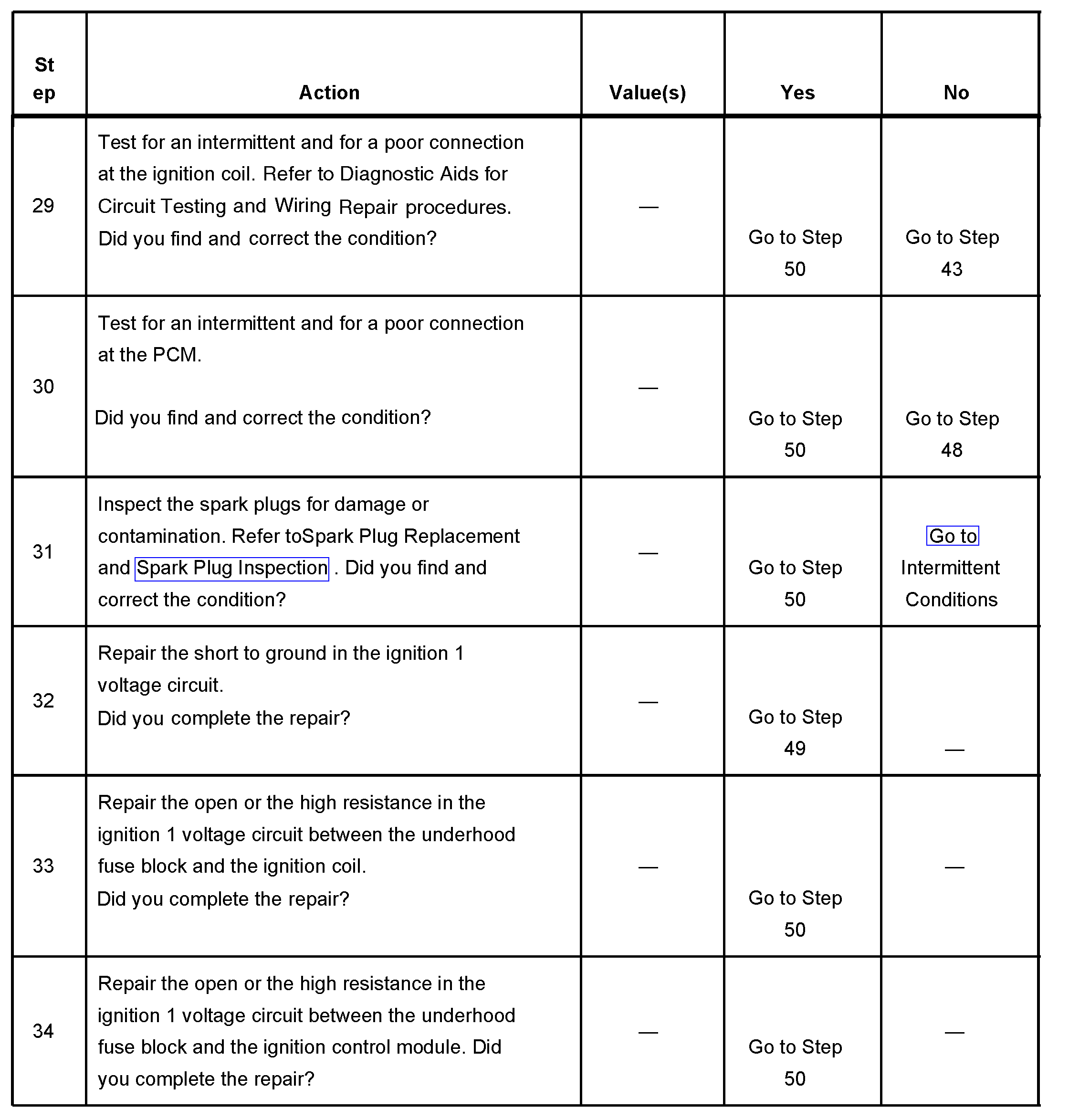
Steps 29-34
pic 8
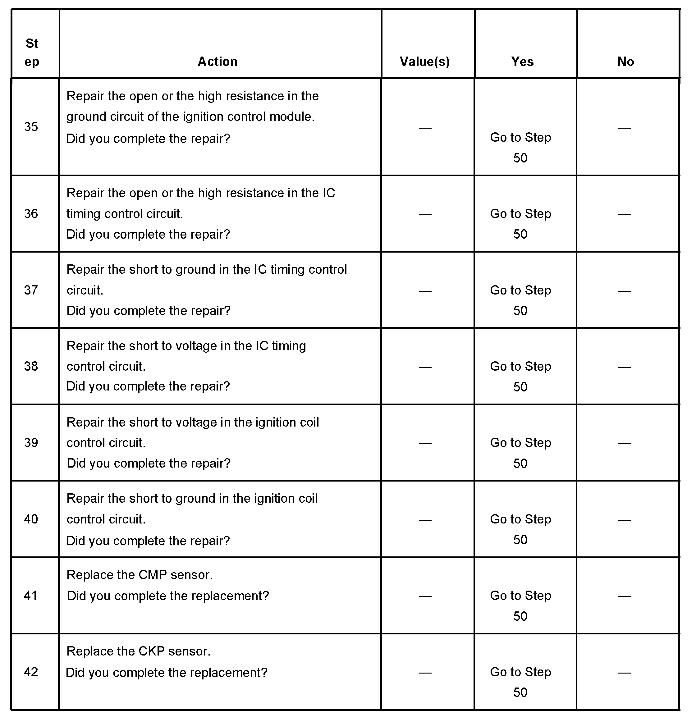
Steps 35-42
pic 9
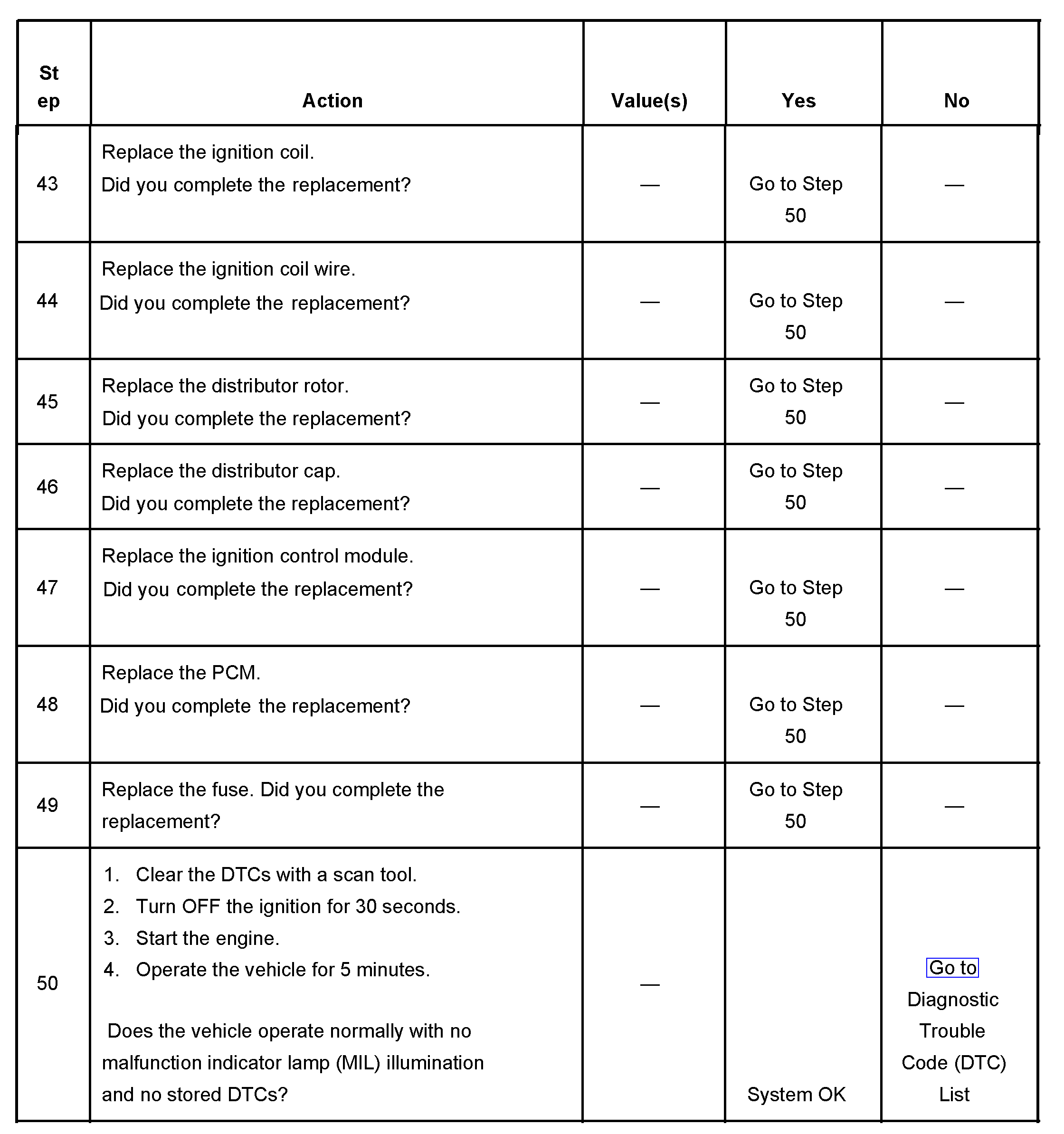
Steps 43-50
pic 10
The numbers below refer to the step numbers on the diagnostic table.
3. This step is testing for a crankshaft position sensor (CKP) signal to the PCM.
4. This step is testing for an internally shorted camshaft position sensor.
9. This step is testing for spark output at more than one spark plug wire. The J-26792 requires a minimum of 25,000 volts to operate.
10. This step determines if spark is being delivered to the distributor cap.
20. This test is testing if the PCM is providing a timing control signal to the ignition control module.
21. This test checks for a basic engine mechanical problem.
_____________________________________
Let me know if this helps or if you have other questions.
Take care,
Joe
Images (Click to make bigger)
Friday, December 18th, 2020 AT 8:43 PM