Hi,
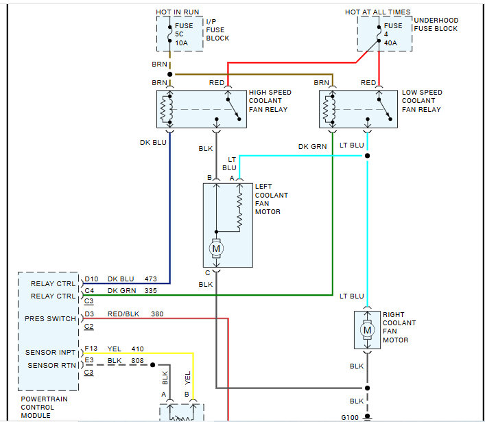
I attached the wiring schematic below so you would have a reference. First, there are two fuses that need checking. One is in the under-hood fuse box (fuse 4), and the other is in the vehicle under the dash (fuse 5C). When you check them, make sure there is power to and from them. The fuse under the hood actually sends power to the fans. The one in the vehicle controls the primary side of the blower motor relays via the PCM, providing a ground path to complete the circuit. If that fuse is faulty, the relay is faulty, or the PCM isn't providing the ground path to complete the circuit, the fans will not run.
So, if fuses are good, the next things I recommend checking are the fan relays. There are two. We need confirmation that power is present on the relay secondary sides of both. Again, both secondary sides get power from fuse 4 under the hood.
Here is a link that explains in detail how to check the relays:
https://www.2carpros.com/articles/how-to-check-an-electrical-relay-and-wiring-control-circuit
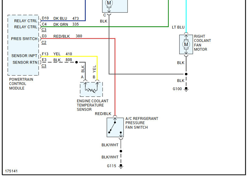
If you get to this point and the relays are good and have power, check for a ground path being provided by the PCM. At the PCM, two wires provide that path. One is dark green, and the other is dark blue. Using a test light, attach the alligator clip side to the battery positive. Then, probe one of those wires at a time. When the temperature is reached to actuate the fan, the ground path should be provided via the PCM, which will turn on the test light. If it doesn't turn on, the problem is within the PCM.
Let me know if this helps or if you have additional questions.
Take care,
Joe
See pics below. Note, I had to cut the schematic in half to make it readable. I did overlap the two so you can follow from one to the next.
Images (Click to make bigger)
Monday, May 26th, 2025 AT 7:05 PM


