Ouch! That isn't fun. This one requires timing chains to be removed as well. Here are the extensive directions. The pics correlate with the directions. The install will be the reverse of removal. After the removal directions, I am going to add torque specs. The remaining pics will correlate with the torque information. Note that step one (according to the directions) is remove engine.
_________________________________________
2005 Ford Truck E 150 V8-5.4L SOHC VIN L
Removal
Vehicle Engine, Cooling and Exhaust Engine Cylinder Head Assembly Service and Repair Procedures Removal
REMOVAL
Cylinder Heads
Part 1
pic 1
Part 2
pic 2
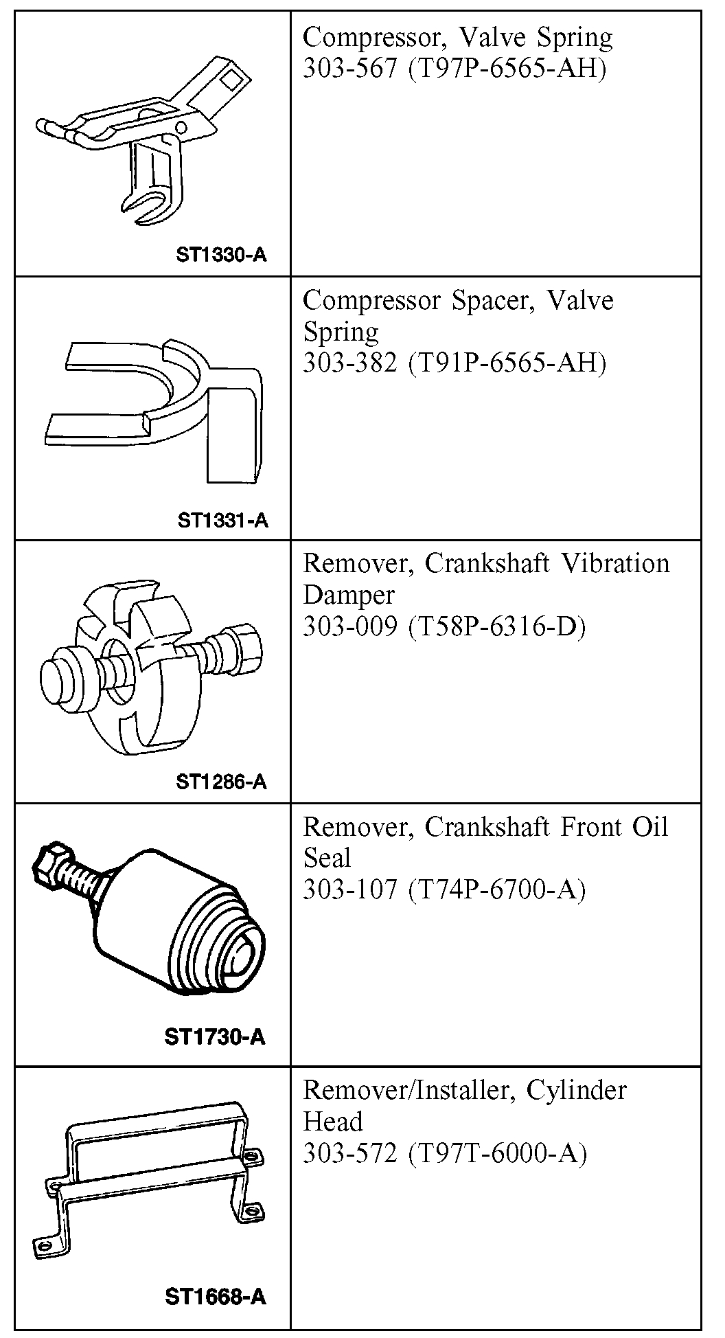
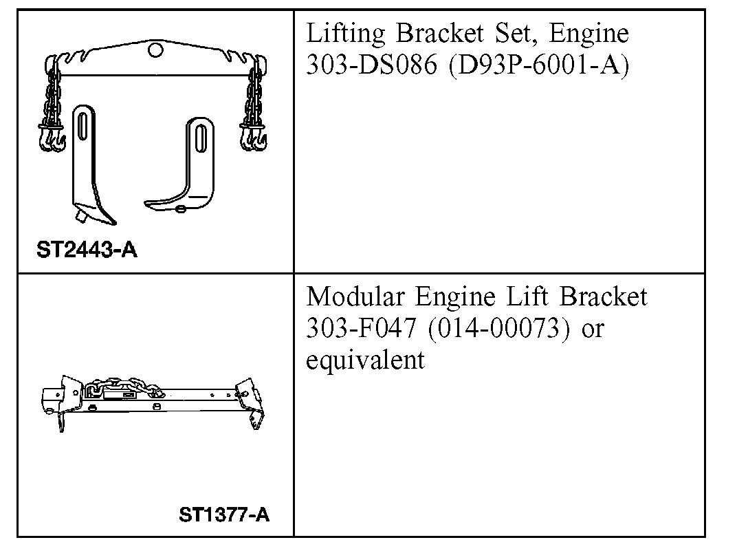
Special Tool(s)
pic 3
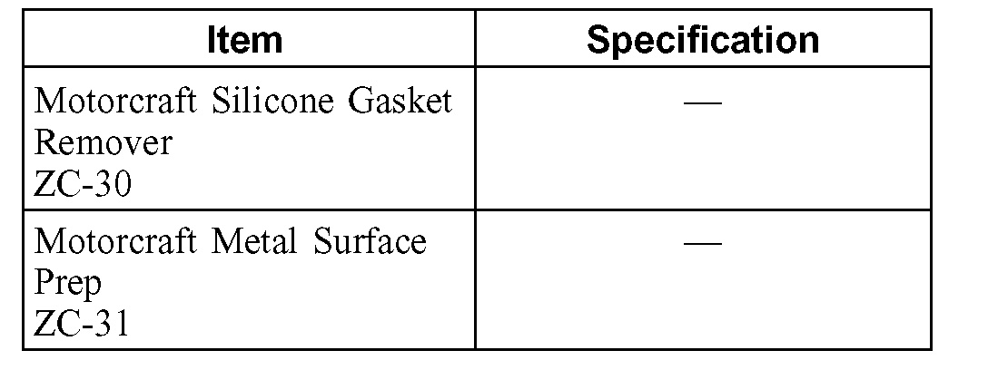
Material
Removal
All cylinder heads
1. Remove the engine.
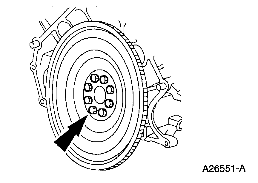
pic 4
2. Remove the bolts and the flexplate.
3. CAUTION: To prevent damage to the oil pan, use care when lowering the engine.
Lower the engine onto wooden blocks.
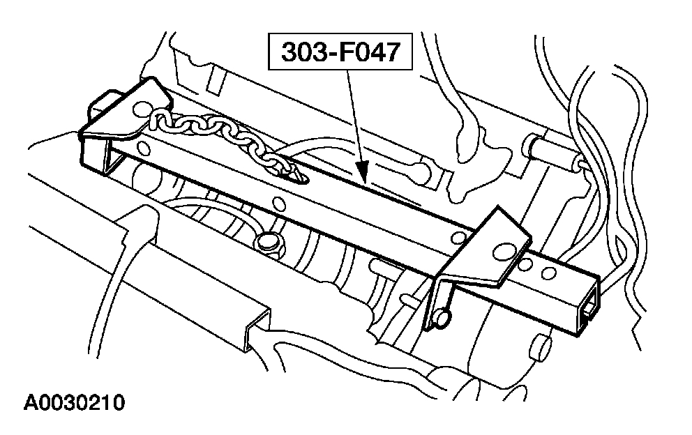
pic 5
4. Remove the special tool.
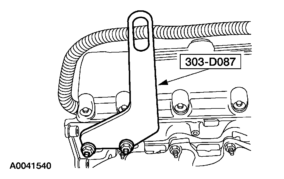
pic 6
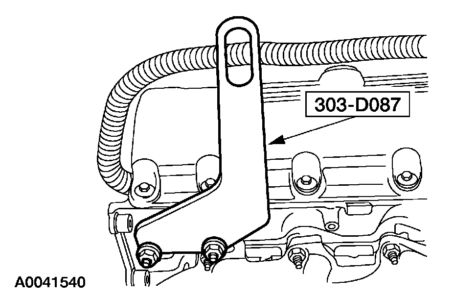
5. Install the special tool.
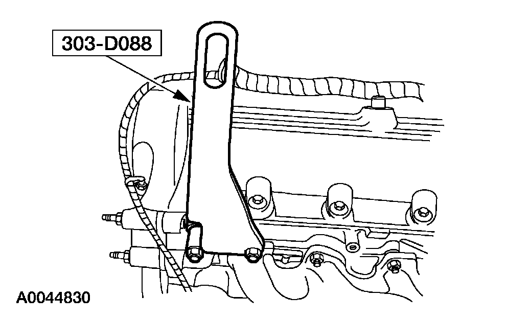
pic 7
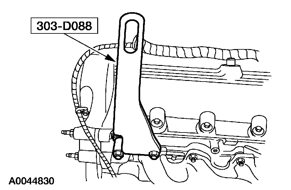
6. Install the special tool.
7. Mount the engine on a suitable work stand.
pic 8
8. Remove the special tool.
pic 9
9. Remove the special tool.
pic 10
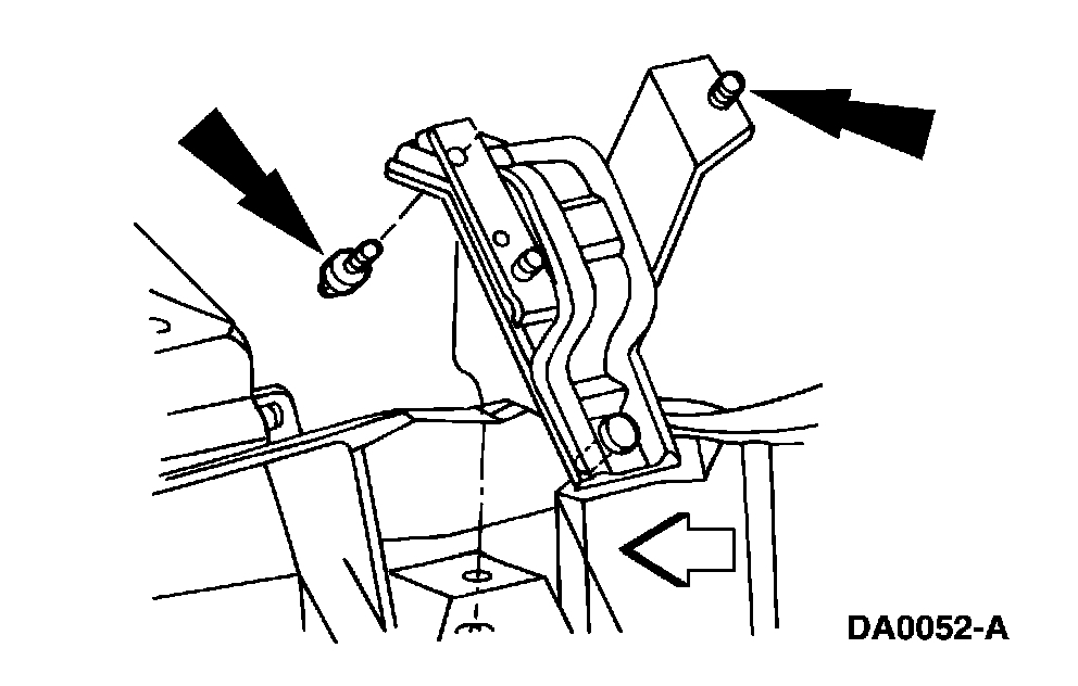
10. Remove the RH engine mount.
pic 11
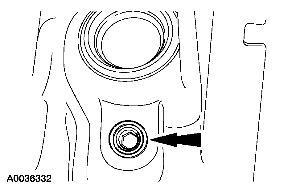
11. NOTE: LH shown; RH similar.
Remove the cylinder block drain plugs, and drain the coolant in a suitable container.
pic 12
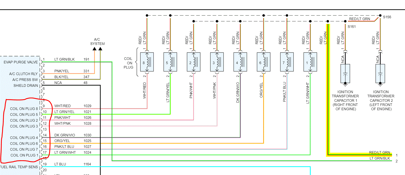
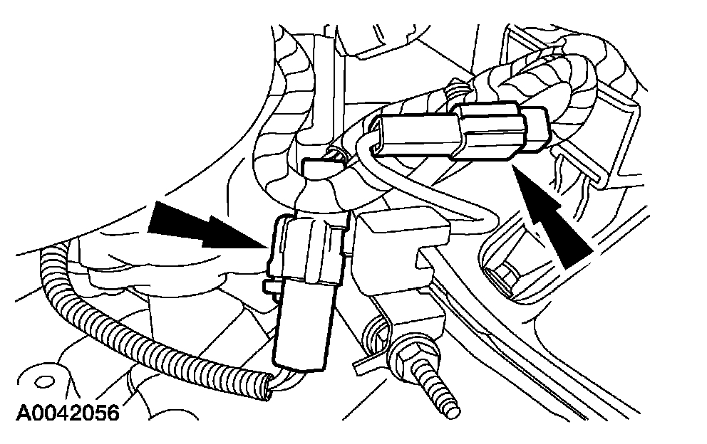
12. Disconnect the LH radio frequency interference capacitor and Cylinder Head Temperature (CHT) sensor electrical connectors.
pic 13
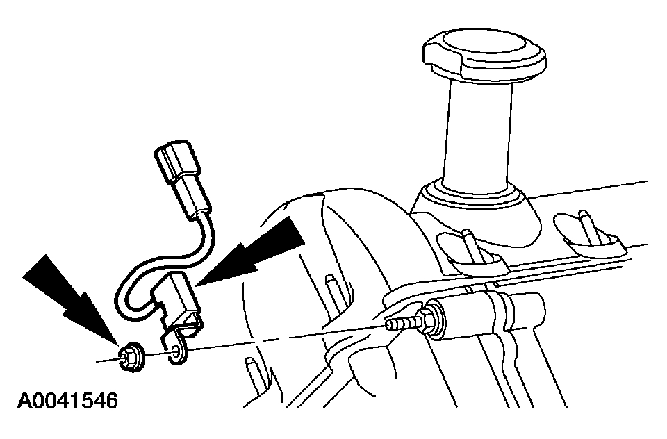
13. Disconnect the Camshaft Position (CMP) sensor electrical connector.
pic 14
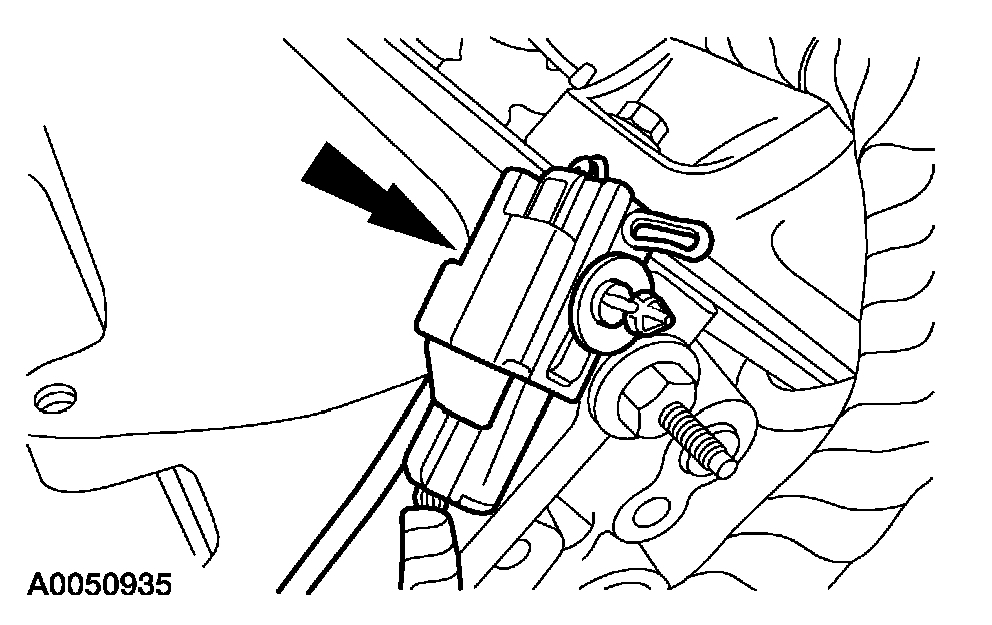
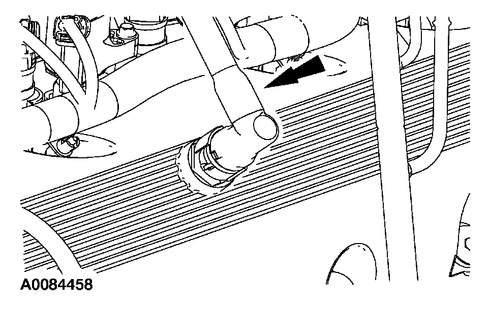
14. Disconnect the RH radio frequency interference capacitor electrical connector.
pic 15
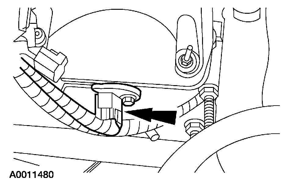
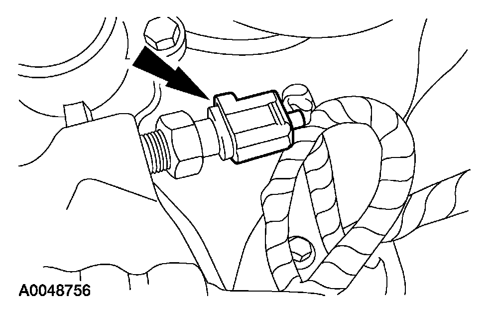
15. Disconnect the knock sensor electrical connector.
pic 16
16. Disconnect the Crankshaft Position (CKP) sensor electrical connector.
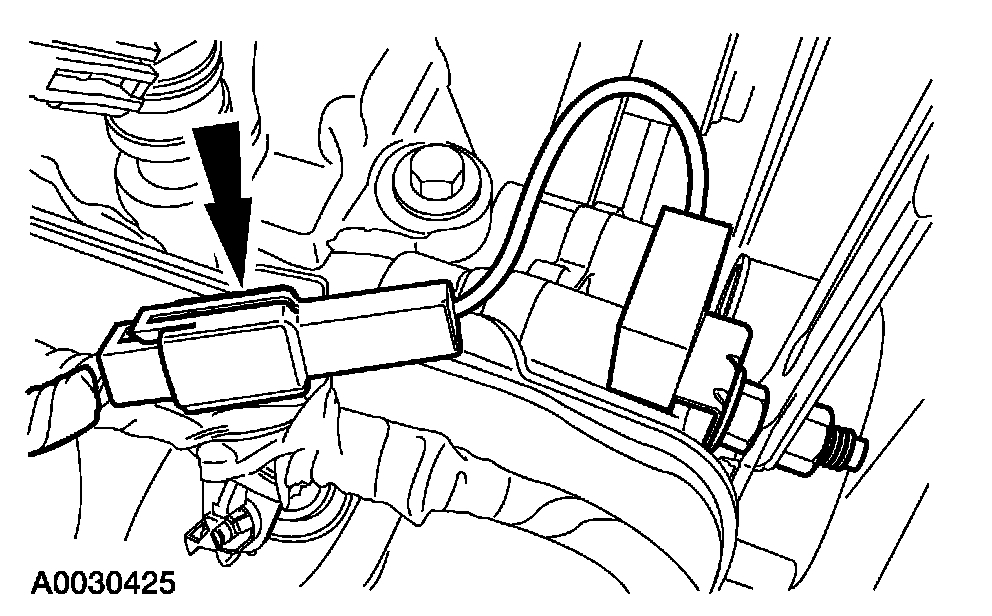
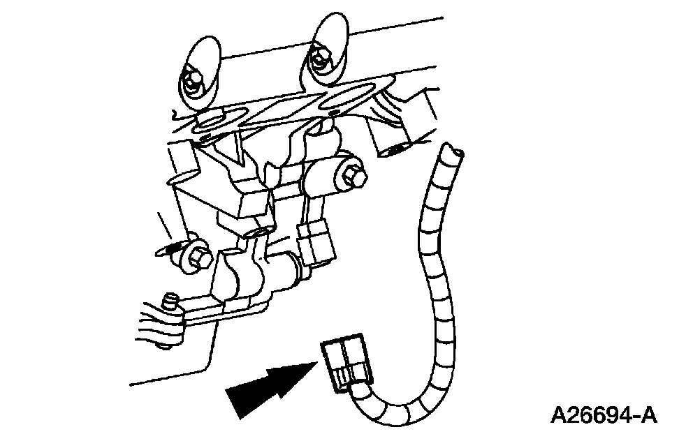
pic 17
17. Disconnect the oil pressure switch electrical connector.
18. Disconnect all of the harness routing clips and connector retainers. Remove the engine control sensor wiring harness.
pic 18
19. NOTE: RH shown; LH similar.
Remove the nuts and the two radio interference capacitors.
pic 19
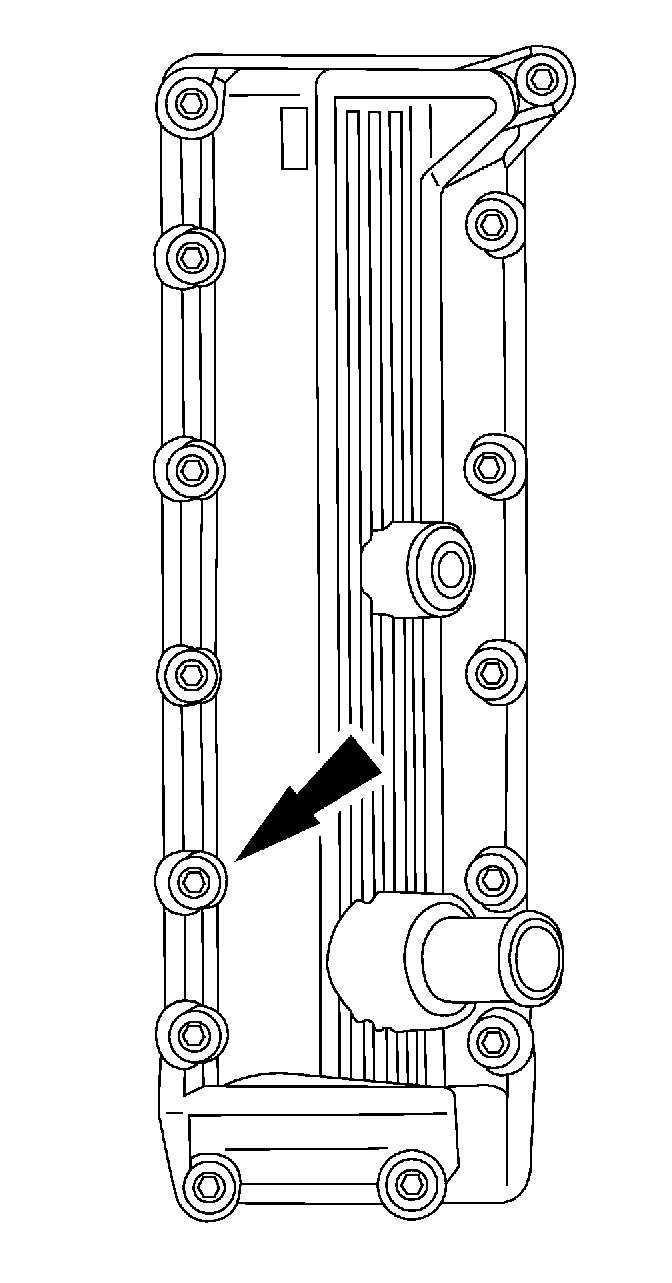
20. Remove the crankcase ventilation tube from the LH valve cover.
pic 20
21. CAUTION: Do not use metal scrapers, wire brushes, power abrasive discs or other abrasive means to clean the sealing surfaces. These tools cause scratches and gouges which make leak paths. Use a plastic scraping tool to remove all traces of old sealant.
NOTE: The bolts are part of the valve cover and should not be removed.
Remove the LH valve cover.
^ Fully loosen the bolts and remove the valve cover.
^ Clean the valve cover mating surface of the cylinder head with silicone gasket remover and metal surface prep. Follow the directions on the packaging.
^ Inspect the valve cover gasket. If the gasket is damaged, remove and discard the gasket. Clean the valve cover gasket groove with soap and water or a suitable solvent.
pic 21
22. CAUTION: Do not use metal scrapers, wire brushes, power abrasive discs or other abrasive means to clean the sealing surfaces. These tools cause scratches and gouges which make leak paths. Use a plastic scraping tool to remove all traces of old sealant.
NOTE: The bolts are part of the valve cover and should not be removed.
Remove the RH valve cover.
^ Fully loosen the bolts and remove the valve cover.
^ Clean the valve cover mating surface of the cylinder head with silicone gasket remover and metal surface prep. Follow the directions on the packaging.
^ Inspect the valve cover gasket. If the gasket is damaged, remove and discard the gasket. Clean the valve cover gasket groove with soap and water or a suitable solvent.
pic 22
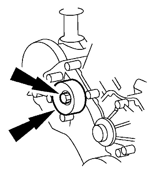
23. Remove the bolt and the belt idler pulley.
pic 23
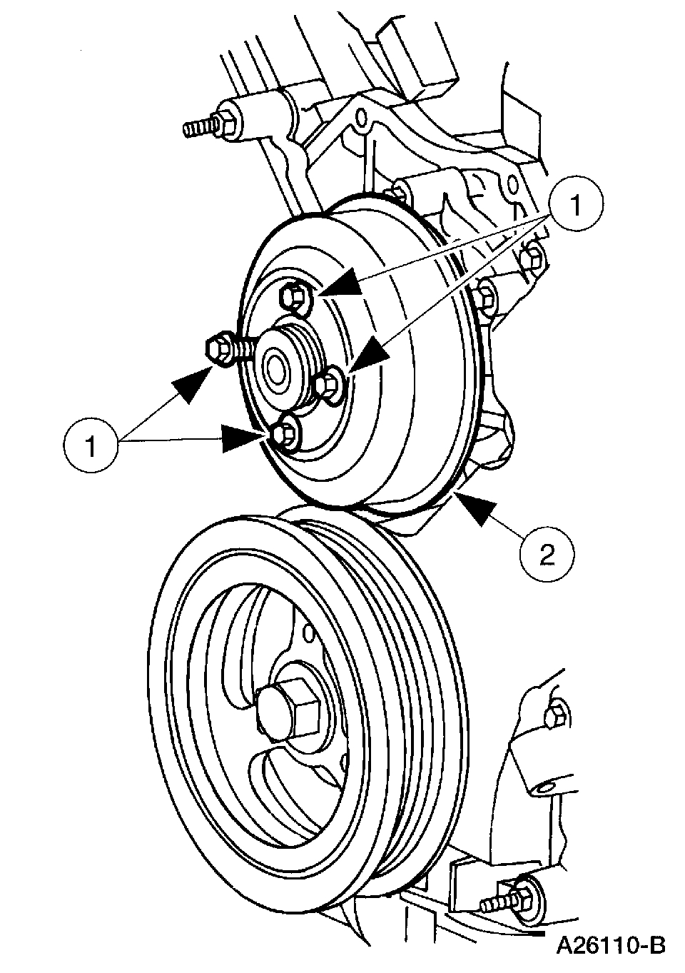
24. Remove the coolant pump pulley.
1 Remove the bolts.
2 Remove the coolant pump pulley.
pic 24
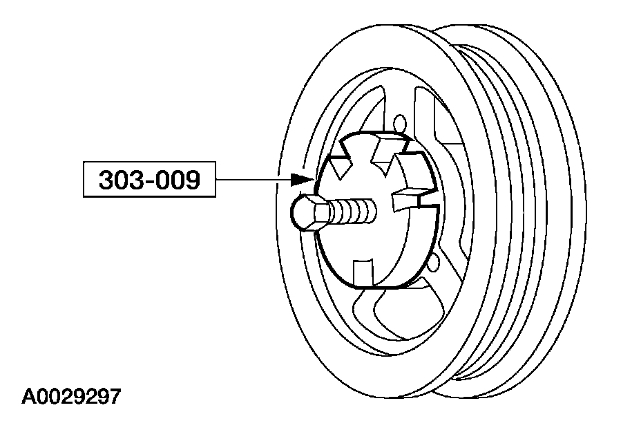
25. Remove and discard the crankshaft pulley bolt.
Use the special tool to remove the crankshaft pulley.
pic 25
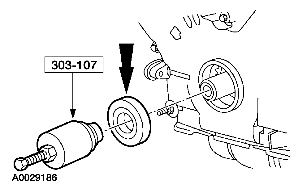
26. Use the special tool to remove the crankshaft front seal.
pic 26
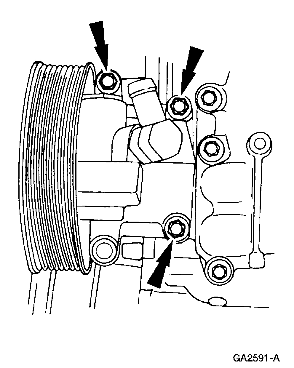
27. Remove the power steering pump.
pic 27
28. Remove the bolts.
pic 28
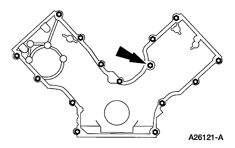
29. NOTE: Correct fastener location is essential for assembly procedure. Record fastener location.
Remove the fasteners.
pic 29
30. Remove the engine front cover from the cylinder block.
pic 30
31. Remove the crankshaft sensor ring from the crankshaft.
32. CAUTION: Use care when removing the spark plugs.
NOTE: Use compressed air to remove any foreign material from the spark plug well before removing the spark plugs.
Remove the eight spark plugs.
pic 31
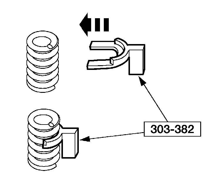
33. Install the special tool between the valve spring coils to prevent valve stem seal damage.
pic 32
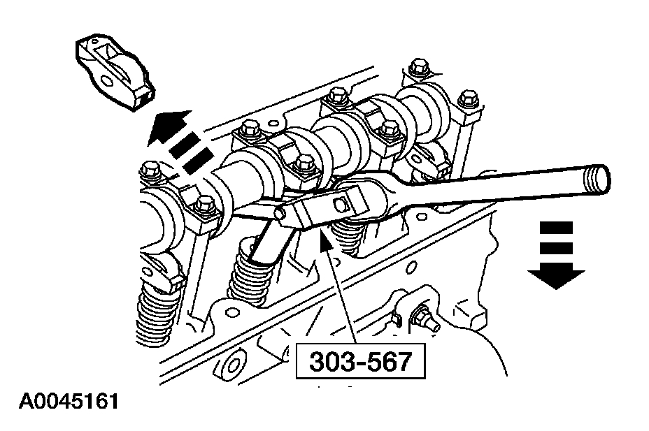
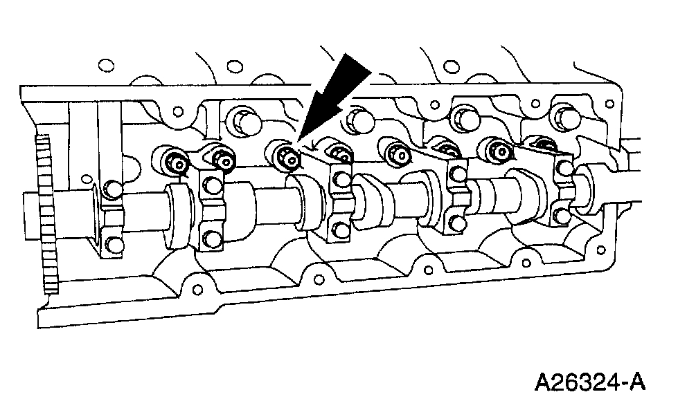
34. NOTE: The camshaft roller followers must be reinstalled in their original locations. Record the camshaft roller follower locations.
NOTE: Position the cam lobe away from the camshaft roller follower prior to removing each camshaft roller follower.
Use the special tool to compress the valve springs, and remove the camshaft roller followers.
pic 33
35. Position the crankshaft with the keyway at the 12 o'clock position.
pic 34
36. CAUTION: If one or both of the tensioner mounting bolts are loosened or removed, the tensioner-sealing bead must be inspected for seal integrity. If cracks, tears, separation from the tensioner body or permanent compression of the seal bead is observed, install a new tensioner.
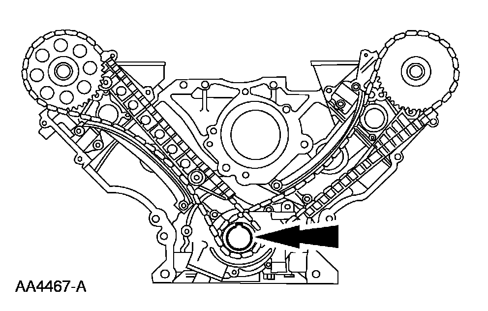
Remove the timing chain tensioning system from both timing chains.
1 Remove the bolts.
2 Remove the timing chain tensioners.
3 Remove the timing chain tensioner arms.
pic 35
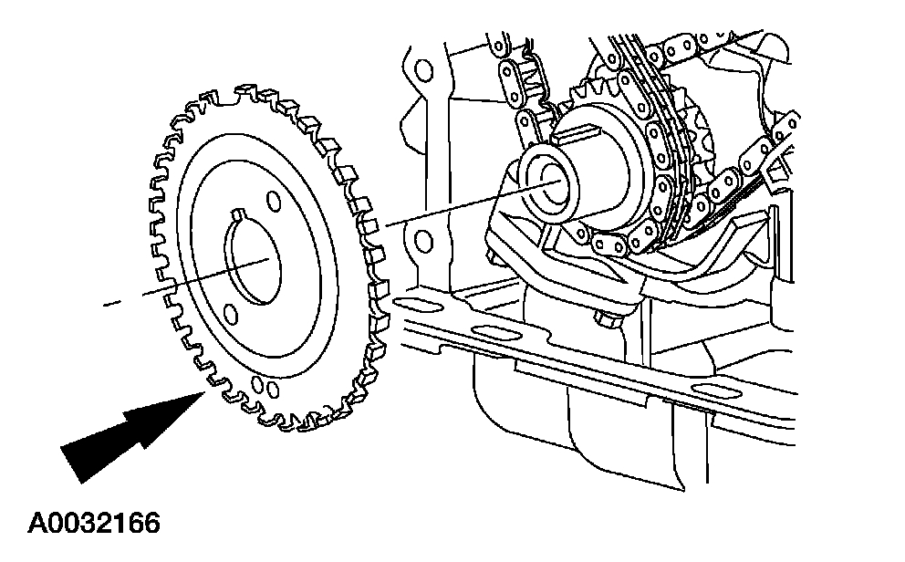
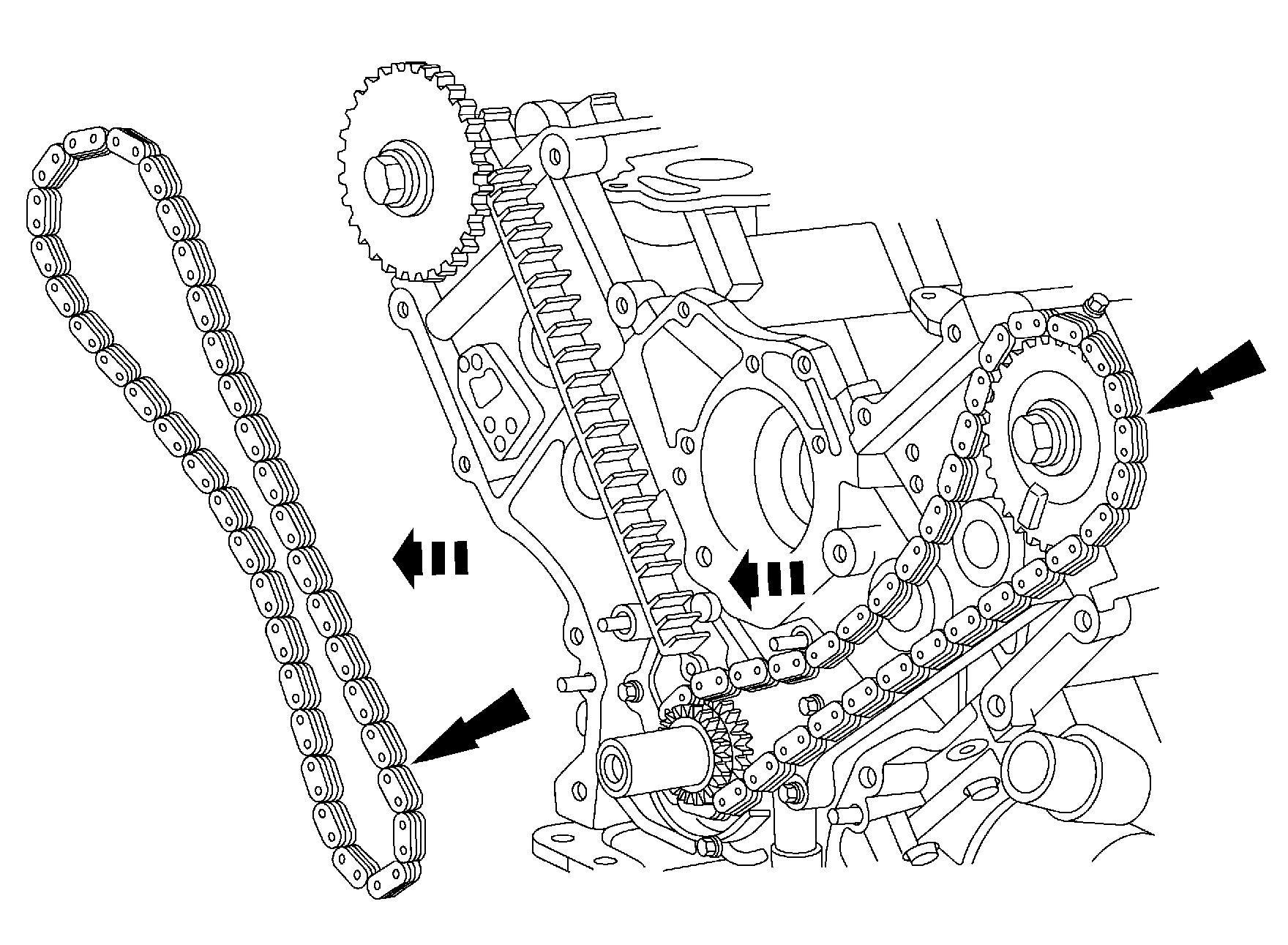
37. Remove the RH and LH timing chains and the crankshaft sprocket(s).
^ Remove the RH timing chain from the camshaft sprocket.
^ Remove the RH timing chain from the crankshaft sprocket.
^ Remove the LH timing chain from the camshaft sprocket.
^ Remove the LH timing chain and crankshaft sprocket(s).
pic 36
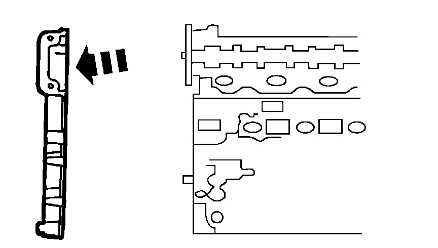
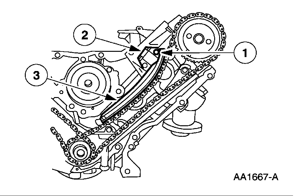
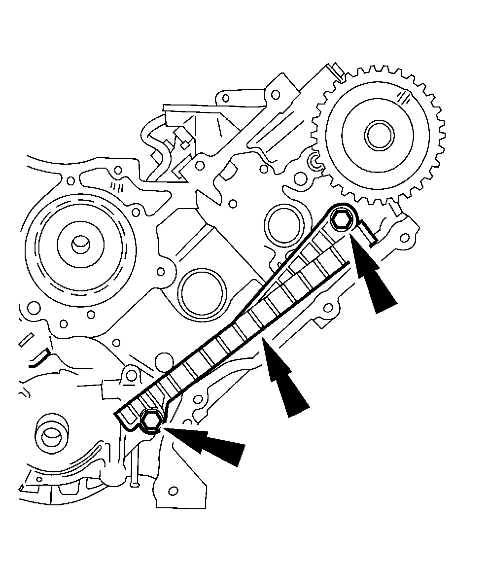
38. Remove both timing chain guides.
^ Remove the bolts.
^ Remove both timing chain guides.
RH cylinder head
pic 37
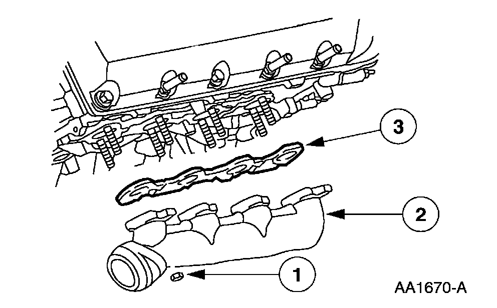
39. Remove the RH exhaust manifold.
1 Remove the nuts.
2 Remove the RH exhaust manifold.
3 Remove the RH exhaust manifold gasket.
LH cylinder head
pic 38
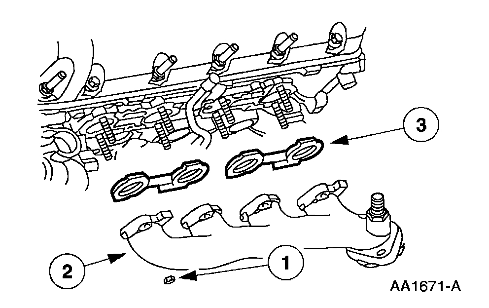
40. Remove the LH exhaust manifold.
1 Remove the nuts.
2 Remove the LH exhaust manifold.
3 Remove the LH exhaust manifold gasket.
pic 39
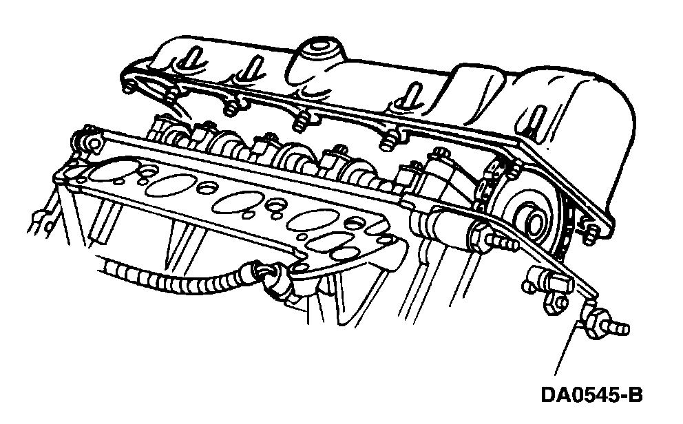
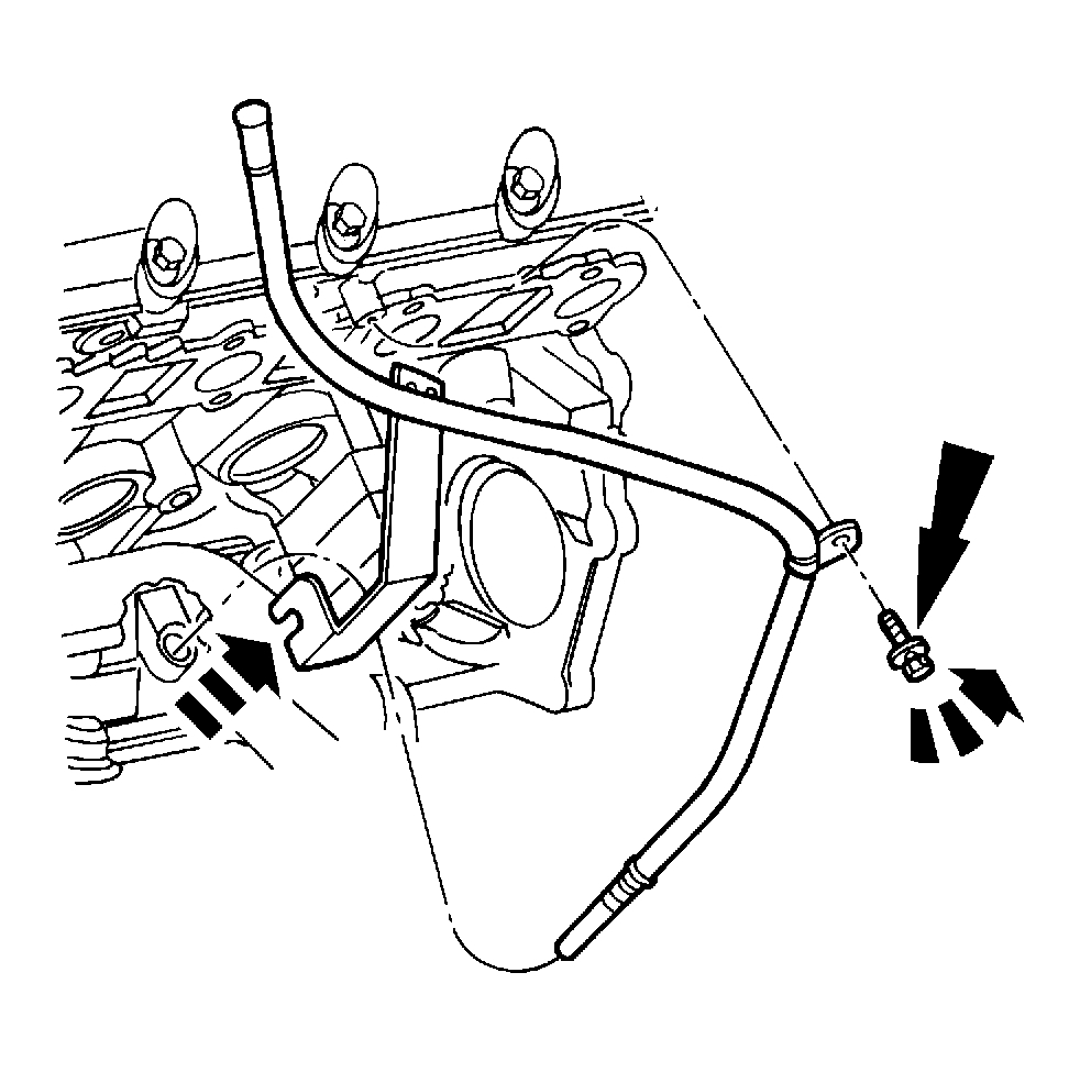
41. Remove the bolt and the oil level indicator tube.
All cylinder heads
42. Clean and inspect the exhaust manifolds.
pic 40
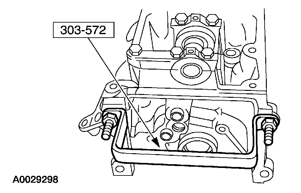
43. Install the special tools on both ends of the cylinder head.
pic 41
44. NOTE: The hydraulic lash adjusters must be reinstalled in their original locations. Record the hydraulic lash adjuster locations.
Remove the hydraulic lash adjusters.
RH cylinder head
pic 42
45. CAUTION: The cylinder head must be cool before removing it from the engine. Cylinder head warpage can result if a warm or hot cylinder head is removed.
CAUTION: Place clean shop towels over exposed engine cavities. Carefully remove the towels so foreign material is not dropped into the engine.
CAUTION: The cylinder head bolts must be discarded and new bolts installed. They are tighten-to-yield designed and cannot be reused.
CAUTION: Do not use metal scrapers, wire brushes, power abrasive discs or other abrasive means to clean the sealing surfaces. These tools cause scratches and gouges that make leak paths. Use a plastic scraping tool to remove all traces of the head gasket.
CAUTION: Aluminum surfaces are soft and can be scratched easily. Never place the cylinder head gasket surface, unprotected, on a bench surface.
Remove the bolts and the RH cylinder head.
^ Discard the cylinder head gasket.
^ Discard the cylinder head bolts.
LH cylinder head
pic 43
46. CAUTION: The cylinder head must be cool before removing it from the engine. Cylinder head warpage can result if a warm or hot cylinder head is removed.
CAUTION: Place clean shop towels over exposed engine cavities. Carefully remove the towels so foreign material is not dropped into the engine.
CAUTION: The cylinder head bolts must be discarded and new bolts installed. They are tighten-to-yield designed and cannot be reused.
CAUTION: Do not use metal scrapers, wire brushes, power abrasive discs or other abrasive means to clean the sealing surfaces. These tools cause scratches and gouges that make leak paths. Use a plastic scraping tool to remove all traces of the head gasket.
CAUTION: Aluminum surfaces are soft and can be scratched easily. Never place the cylinder head gasket surface, unprotected, on a bench surface.
Remove the bolts and the LH cylinder head.
^ Discard the cylinder head gasket.
^ Discard the cylinder head bolts.
All cylinder heads
47. CAUTION: Do not use metal scrapers, wire brushes, power abrasive discs or other abrasive means to clean the sealing surfaces. These tools cause scratches and gouges that make leak paths. Use a plastic scraping tool to remove all traces of the head gasket.
CAUTION: Observe all warnings or cautions and follow all application directions contained on the packaging of the silicone gasket remover and the metal surface prep.
NOTE: If there is no residual gasket material present, metal surface prep can be used to clean and prepare the surfaces.
Clean the cylinder head-to-cylinder block mating surfaces of both the cylinder head and the cylinder block.
1 Remove any large deposits of silicone or gasket material with a plastic scraper.
2 Apply silicone gasket remover, following package directions, and allow to set for several minutes.
3 Remove the silicone gasket remover with a plastic scraper. A second application of silicone gasket remover may be required if residual traces of silicone or gasket material remain.
4 Apply metal surface prep, following package directions, to remove any remaining traces of oil or coolant, and to prepare the surfaces to bond with the new gasket. Do not attempt to make the metal shiny. Some staining of the metal surfaces is normal.
pic 44
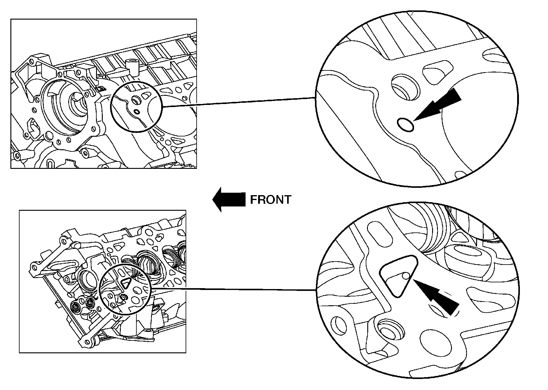
48. NOTE: Make sure all cylinder head surfaces are clear of any gasket material, RTV, oil and coolant. The cylinder head surface must be clean and dry before running a flatness check.
NOTE: Use a straightedge that is calibrated by the manufacturer to be flat with 0.005 mm (0.0002 inch) per running foot length. For example, if the straightedge is 61 cm (24 inch) long, the machine edge must be flat with 0.010 mm (0.0004 inch) from end to end.
NOTE: LH is shown; RH is similar.
Support the cylinder head on a bench with the head gasket side up. Inspect all areas of the deck face with a straightedge, paying particular attention to the oil pressure feed area. The cylinder head must not have depressions deeper than 0.0254 mm (0.001 inch) across a 38.1 mm (1.5 inch) square area or scratches more than 0.0254 mm (0.001 inch).
__________________________________
Torque Specs
2005 Ford Truck E 150 V8-5.4L SOHC VIN L
Mechanical (including Torque)
Vehicle Engine, Cooling and Exhaust Engine Cylinder Head Assembly Specifications Mechanical (including Torque)
MECHANICAL (INCLUDING TORQUE)
Cylinder head flatness must be within .................... 0.0254 mm (0.001 inch) across a 38.1 mm (1.5 inch) square area.
pic 45
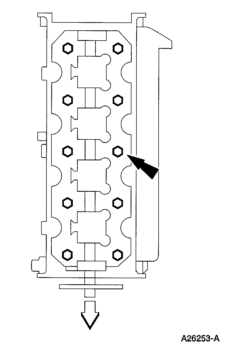
LH cylinder head
NOTE: Replace bolts
Stage 1: Tighten to .................... 40 Nm (30 ft. lbs.).
Stage 2: Tighten an additional .................... 90 degrees.
Stage 3: Tighten an additional .................... 90 degrees.
pic 46
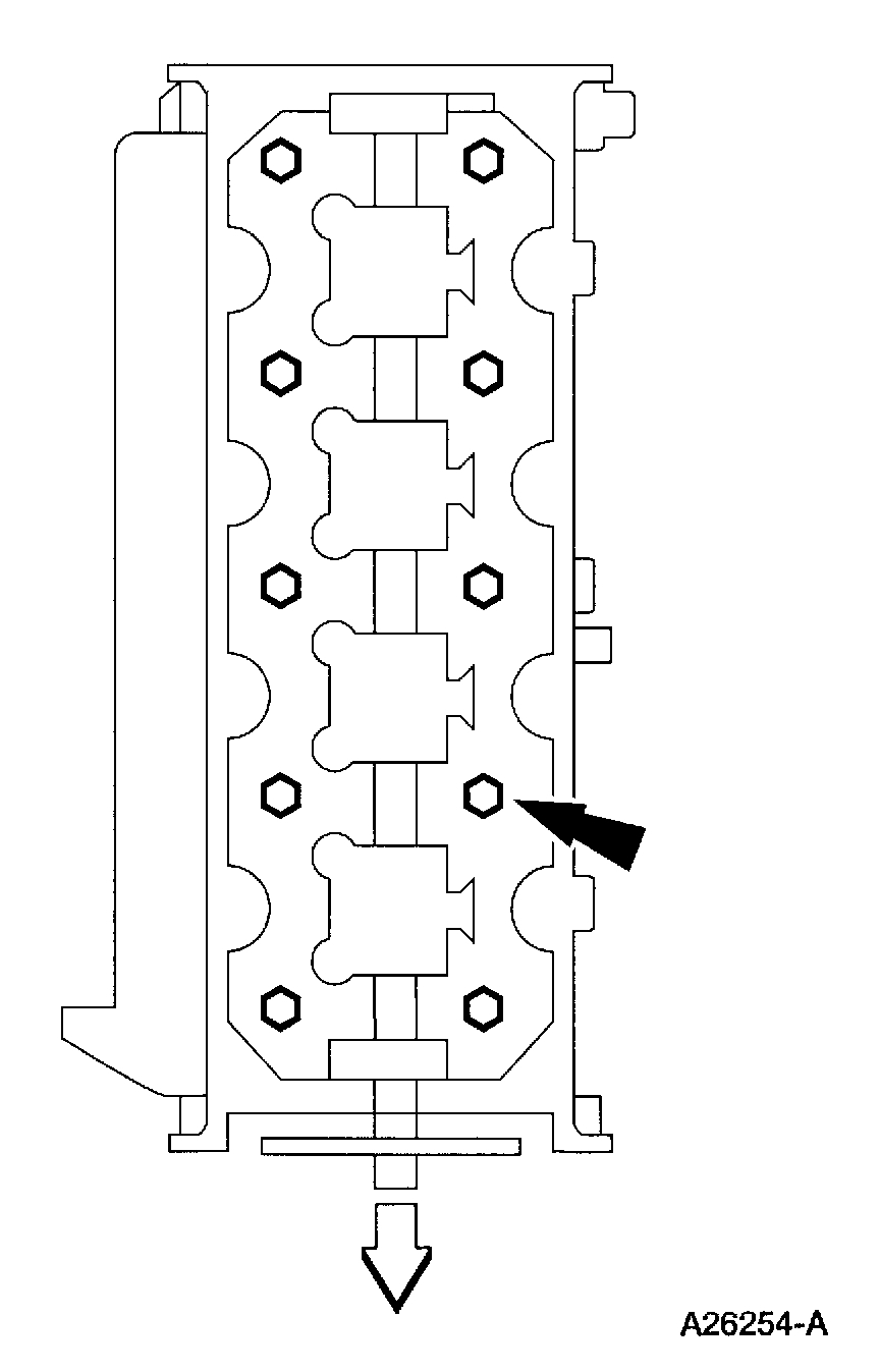
RH cylinder head
NOTE: Replace bolts
Stage 1: Tighten to .................... 40 Nm (30 ft. lbs.).
Stage 2: Tighten an additional .................... 90 degrees.
Stage 3: Tighten an additional .................... 90 degrees.
pic 47
Intake Manifold
Stage 1: Tighten to .................... 2 Nm (18 inch lbs.).
Stage 2: Tighten to .................... 25 Nm (18 ft. lbs.).
pic 48
Camshaft bearing caps .................... 10 Nm (89 in.lbs.).
Camshaft Sprocket
Stage 1: Tighten to .................... 40 Nm (30 ft. lbs.).
Stage 2: Tighten an additional .................... 90 degrees.
pic 49
RH Exhaust manifold bolts .................... 25 Nm (18 ft.lbs.).
pic 50
LH Exhaust manifold bolts .................... 25 Nm (18 ft.lbs.).
__________________________________
Let me know if you have questions or have any questions.
Take care,
Joe
Images (Click to enlarge)
May 20, 2020 at 8:30 PM