Code PO500 speed sensor A location needed

Tiny
SBARGER
  • MEMBER
  • 2005 MAZDA 3
  • 2.0L
  • 4 CYL
  • 2WD
  • MANUAL
  • 140 MILES
This is my first time owning a Mazda. Got this car, clutch was great, nothing leaking or running weird, next day I go to drive it and the battery is dead. My problem is only beginning, my speedometer and odometer is now not working. My fuse blew in my wipers after I had the battery replaced and then had to figure out the bad connections (low voltage from cables, so they shimmed it). Then the blower motor relay blew, froze out December thinking it was the motor (found the relay on my own without the help of the mechanic that said it was the motor). Where is the location to speed sensor A? What would the voltage be if the sensor is good? It's now running rich (Code P2188), so MAF sensor or harness? This whole bottom is rusted out the previous owner had it spray foamed and painted the color of the car. Already lost a strut mount. Yes I got a dud.
Monday, January 13th, 2020 AT 2:39 PM

3 Replies

Tiny
JACOBANDNICKOLAS
  • MECHANIC
  • 108,192 POSTS
It is located on the lower portion of the transmission. You need to remove the battery cover duct to see it. Here are the directions for replacement. The attached pics correlate with the directions.

2005 Mazda 3 L4-2.0L
Vehicle Speed Sensor (VSS) Removal/Installation
Vehicle Powertrain Management Sensors and Switches - Powertrain Management Sensors and Switches - Computers and Control Systems Vehicle Speed Sensor Service and Repair Procedures Vehicle Speed Sensor (VSS) Removal/Installation
VEHICLE SPEED SENSOR (VSS) REMOVAL/INSTALLATION

Caution:
Water or foreign material entering the connector can cause a poor connection or corrosion. Be sure not to drop water or foreign material on the connector when disconnecting It.
If foreign materials are stuck to the VSS, disturbance by magnetic flux can cause sensor output to be abnormal and thereby negatively affect control. Make sure that foreign materials such as Iron filings are not stuck to the VSS during installation.

1. Remove the battery duct and battery cover.
2. Disconnect the negative battery cable.
3. Remove the under cover.
4. Disconnect the VSS connector.

Pic 1

5. Remove the VSS.
6. Apply ATF to a new O-ring and install it on a new VSS.

Pic 2

7. Install the VSS.
Tightening torque 8 - 11 Nm (82 - 112 kgf-cm, 71 - 97 inch lbs.)
8. Connect the VSS connector.
9. Install the under cover.
10. Connect the negative battery cable.
11. Install the battery duct and battery cover.

I hope this helps. However, it sounds like you may want to get rid of the vehicle if it is that badly rusted. It could be unsafe.

Joe
Was this
answer
helpful?
Yes
No
Monday, January 13th, 2020 AT 8:30 PM
Tiny
SBARGER
  • MEMBER
  • 3 POSTS
Thanks for the info. I really appreciate all the knowledge! The car frame is solid just the floorboard has a hole then the strut mount. I'm replacing all struts, and the mounts and front ens also just a lot to do. Would the VSS cause the gas to become rich?(P2188)Or should I just check the MAF and harness?
Was this
answer
helpful?
Yes
No
Tuesday, January 14th, 2020 AT 12:33 PM
Tiny
JACOBANDNICKOLAS
  • MECHANIC
  • 108,192 POSTS
Hi,

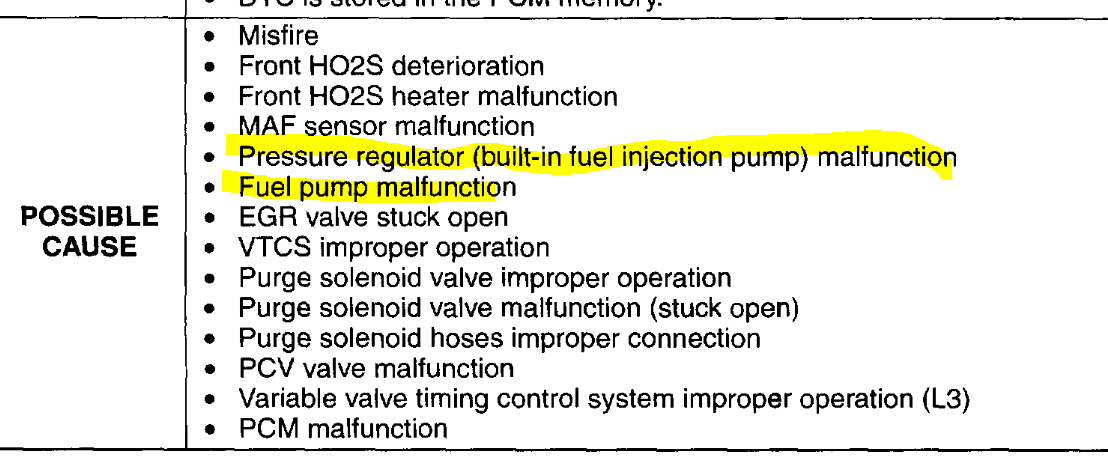
Most commonly, a rich fuel mixture is due to high fuel pressure. If the regulator isn't working properly, it can allow fuel to get higher in pressure than it should. If you look at pic 1, it shows the possible causes for the code you listed. I would start by testing fuel pressure.

Here is a link that explains how in general it is done:

https://www.2carpros.com/articles/how-to-check-fuel-system-pressure-and-regulator

Here are the directions and specifications specific to your vehicle for checking. The remaining pictures correlate with the directions.
__________________________________________________________
2005 Mazda 3 L4-2.0L
Fuel Pressure Test
Vehicle Powertrain Management Fuel Delivery and Air Induction Fuel Pump Fuel Pressure Testing and Inspection Component Tests and General Diagnostics Fuel Pressure Test
FUEL PRESSURE TEST
FUEL LINE PRESSURE INSPECTION

WARNING: Fuel line spills and leakage from the pressurized fuel system are dangerous. Fuel can ignite and cause serious injury or death and damage. To prevent this, complete the following inspection with the engine stopped.

1. Follow "BEFORE SERVICE PRECAUTION" before performing any work operations to prevent fuel from spilling from the fuel system.
2. Disconnect the negative battery cable.
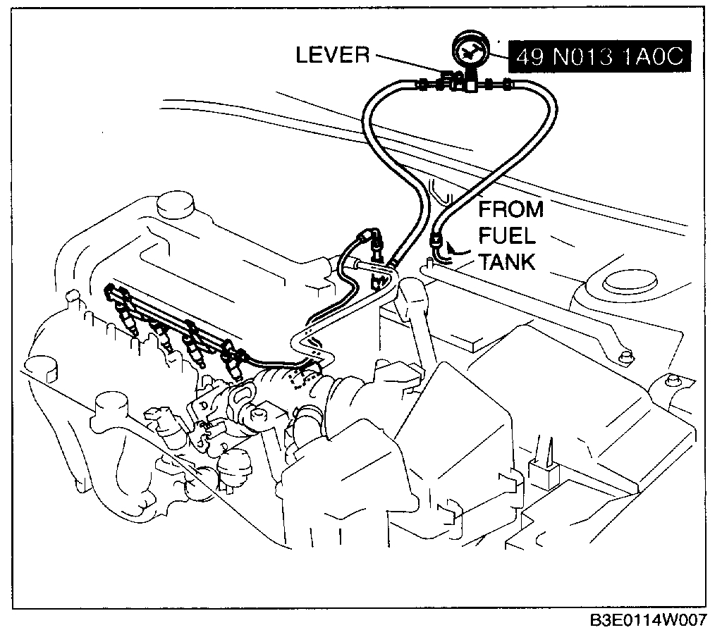
3. Disconnect the quick release connector (in the engine compartment.

pic 2

4. Turn the lever of the SST parallel to the hose as shown in the figure.
5. Insert the SST quick release connector into the fuel pipe until a click is heard.
6. Verify that the quick release connector is firmly connected by pulling it by hand.
7. Start the fuel pump using the following procedure:

Using WDS or equivalent

pic 3

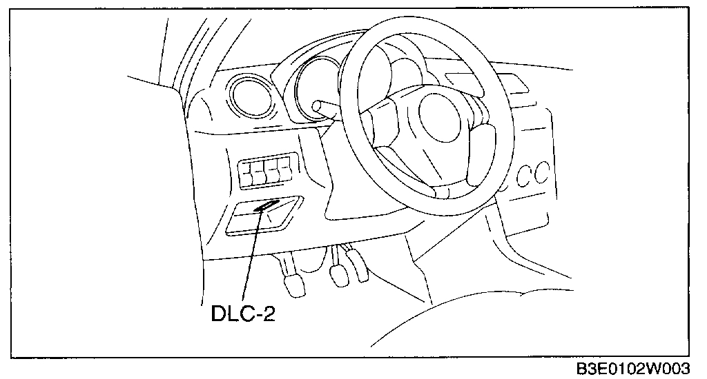
1. Connect the WDS or equivalent to the DLC-2.
2. Start the fuel pump using the "FP" simulation function.

Not using WDS or equivalent

pic 4

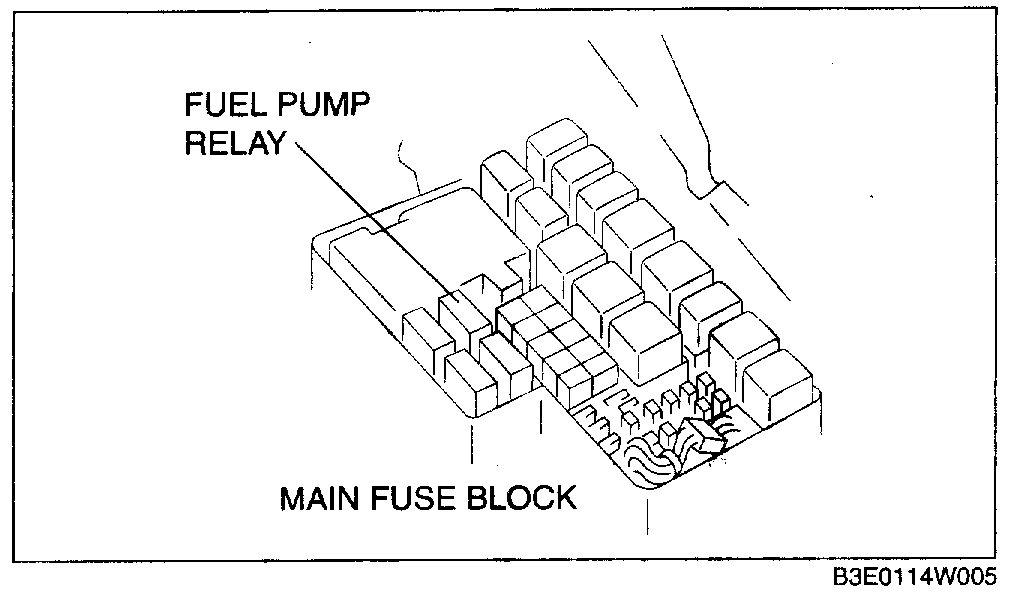
1. Remove the fuel pump relay.

CAUTION: Be careful to short the specified terminal as shorting the wrong terminal of the main fuse block may cause a malfunction.
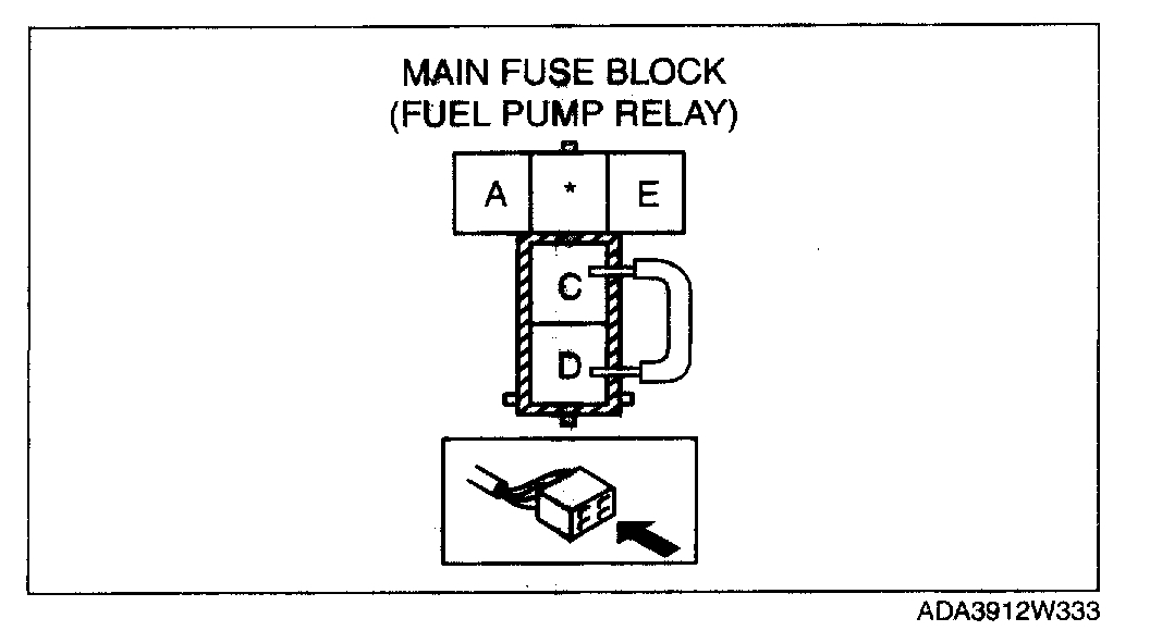
pic 5

2. Using a jumper wire, short fuel pump relay terminals C and D and connect the negative battery cable to start the fuel pump.

8. Operate the fuel pump for 10 s.
9. Measure the fuel line pressure.
- If not within the specification, inspect the following:

If it less than the specification:
- Fuel pump unit
- Fuel line leakage

If it exceeds the specification:
- Pressure regulator

Fuel pressure (Reference)
350 - 410 kPa 3.57 - 4.18 kgf/sq.cm, 50.8 - 59.4 psi

10. Stop the fuel pump using the following procedure:

Using WDS or equivalent
1. Stop the fuel pump using the "FP" simulation function.

Not using WDS or equivalent
1. Disconnect the negative battery cable to stop the fuel pump.

11. Measure the fuel hold pressure after 5 min.
- If not within the specification, inspect the following:
- Fuel line for clogging or leakage

Fuel hold pressure (Reference)
250 kPa 2.55 kgf/sq.cm, 36.2 psi or more

12. Disconnect the SST.
13. Connect the quick release connector.
14. Inspect all related parts by performing "AFTER SERVICE PRECAUTION".

___________________________

Let me know if this helps or if you have other questions.

Take care,
Joe
Was this
answer
helpful?
Yes
No
Tuesday, January 14th, 2020 AT 6:53 PM

Please login or register to post a reply.

Sponsored links