Code 14 - High coolant temperature indicated

Tiny
SCOOTER18
  • MEMBER
  • 1991 CHEVROLET S-10
  • 3.0L
  • V6
  • 2WD
  • MANUAL
  • 250,000 MILES
I have the vehicle listed above with a 4.3 L V6 5 speed. For the past month I have a code 14 (high coolant temperature) code intermittent. So days light comes on as soon as started and doesn't go off and other days might only come on for a second or two and everything in between. I've changed the coolant sensor, flush with fresh coolant, checked connections but still no fix. The truck seems to run okay. I'm thinking a short or grounding issue. But where and how do I check a ground issue with that circuit from the sensor to the ECM? Thanks! Kevin
Friday, May 14th, 2021 AT 2:44 PM

5 Replies

Tiny
CARADIODOC
  • MECHANIC
  • 33,742 POSTS
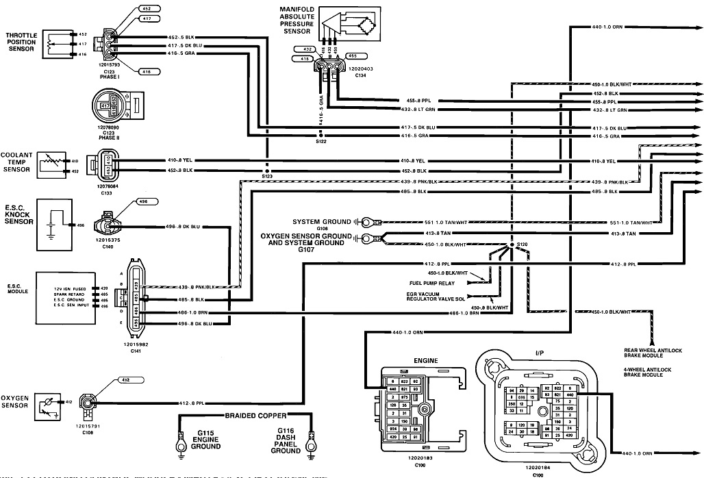
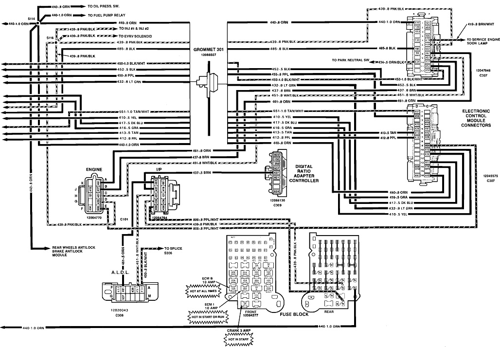
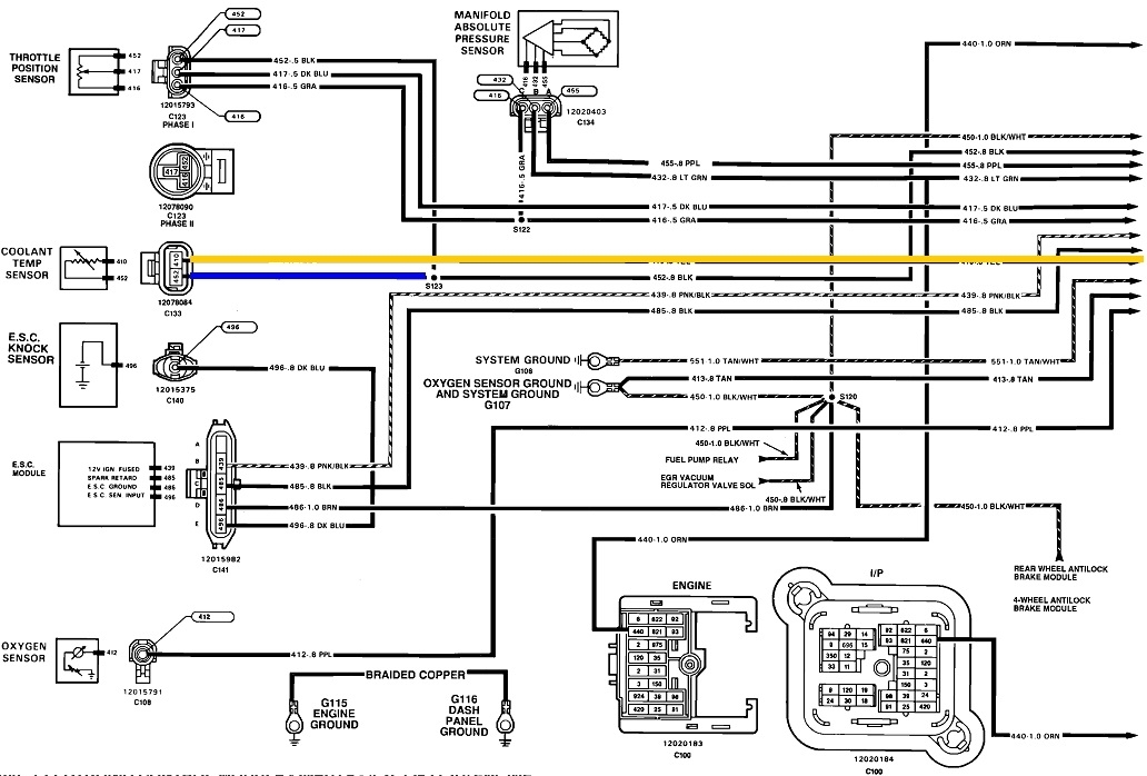
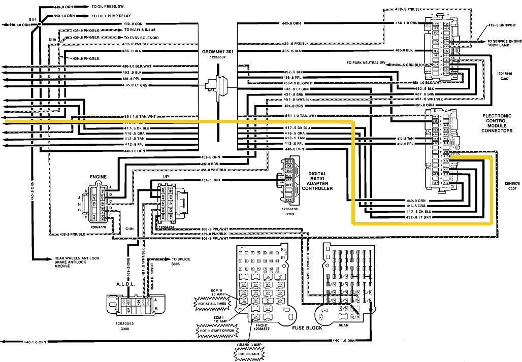
This is rarely caused by the sensor because temperature sensors have just one component inside them. This is almost always a problem with the wiring or connector terminals. These first two diagrams are for the Engine Computer's sensors. The last two are the same, but I highlighted the wires where we're going to find the cause of the problem.

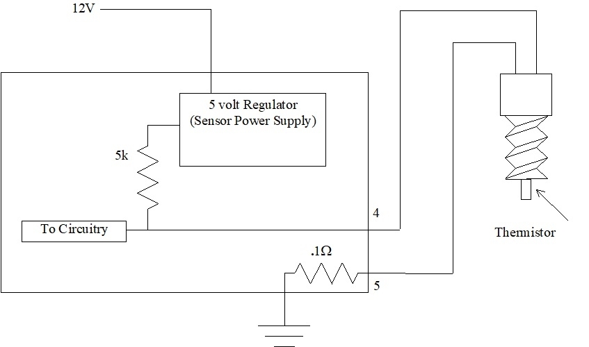
This circuit is fed with a carefully-regulated 5.0 volts from the Engine Computer. There's an internal resistor that drops some of that 5,0 volts, but only when the coolant temperature sensor circuit has no break in it. With that normal operation, the sensor will draw the signal voltage down to between 0.5 and 4.5 volts. Anything outside that range is what gets detected as a defect and sets the diagnostic fault code.

With a break in the circuit, there's no current flow through it, therefore there's no voltage dropped across the internal resistor. That leaves the full 5,0 volts to be seen as the signal voltage, which is outside the acceptable range. The fault code "CTS voltage high" code will be set. At the same time, when you use a digital voltmeter to measure that signal voltage right at the sensor, you're going to find close to 0.0 volts.

For any voltage tests to be valid, you can't create any "open circuits". meaning unplugging anything. You have to back-probe through the back of the connector to take the readings. For the benefit of others researching this topic, here's a link to an article on how to use a digital voltmeter:

https://www.2carpros.com/articles/how-to-use-a-voltmeter

The circuit in question are the wires I highlighted in the last two diagrams. The blue wire is the sensor's ground wire that goes to ground through the computer. From the splice and to the right of the blue section, we don't have to worry about that. The ground wire is shared with the throttle position sensor. If that section had a defect, you'd be getting a fault code for the TPS too.

To verify you're taking readings in the right circuit, back-probe the yellow wire in the CTS connector. The meter's negative probe must be on the battery's negative post or on any clean, rust-free point on the engine. Ignition switch must be in the "run" position. If the problem is not occurring at this time, you're going to find something between 0.5 and 4.5 volts. Typical would be around 2.5 to 3.5 volts. The exact value is unimportant as long as it's not 0.0 or 5.0 volts.

When the problem is occurring, the computer will be seeing 5.0 volts, but you'll measure 0.0 volts at the sensor. Watch the meter while you wiggle and move that yellow wire. You're looking for the area where you can manipulate it and cause the voltage to change. The best suspect is the terminals in the connector itself. Next would probably be where the wires go through the firewall as that section flexes as the engine rocks.

When you get the defect to act up, there's two possible voltages you're going to find at the yellow wire in the CTS connector. That is 5.0 volts or 0.2 volts. Consider 0.2 volts as 0.0 volts. That two tenths is the result of the circuitry inside the computer, and isn't part of this story. There is going to be 5.0 volts from the computer all the way up to the break in the circuit, and 0.0 volts everywhere after that break. If the entire yellow wire is good, you'll find 5.0 volts when you back-probe that terminal in the CTS connector. That means the break has to be in the terminal for the yellow wire, the sensor itself, (unlikely), the terminal for the black wire, or the black wire or a corroded splice. The most likely finding will be 5.0 volts on the yellow wire and 0.0 volts on the black wire. Since you already replaced the sensor, that leaves the two pairs of mating terminals as the logical suspects If you find 0.0 volts on the yellow wire, that wire has the break in it. If interpreting the readings is still confusing, just tell me what you find on the two wires Remember, those readings have to be taken with the connector plugged in.
Was this
answer
helpful?
Yes
No
-1
Friday, May 14th, 2021 AT 7:54 PM
Tiny
SCOOTER18
  • MEMBER
  • 3 POSTS
CARADIODOC, of course this morning the truck won't produce the code but I did back probe the CTS and got readings of 4.2 volts on yellow wire and 0.0 volts on the black.
I'll get back to you with the reading when the code is shown. Thanks so much for your help so far!
Was this
answer
helpful?
Yes
No
Saturday, May 15th, 2021 AT 10:23 AM
Tiny
CARADIODOC
  • MECHANIC
  • 33,742 POSTS
If you monitor the voltage on the yellow wire while the engine is warming up, you should see something interesting. 4.2 volts is typical for a cold engine. As the temperature goes up, that voltage is going to go down to somewhere around 2.5 to 3.5 volts, then suddenly pop back up to something higher. At that point it will resume slowly going down. I'd expect to see around 2.0 volts when the engine reaches normal operating temperature.

This diagram is part of my "Notes Pages" I handed out in the classroom. It shows the 5.0-volt regulated power supply inside the Engine Computer, the 5,000 ohm "dropping resistor", and the temperature sensor with its thermistor inside. That's a temperature-variable resistor. All of that 5.0 volts has to be used up across those two resistors. The 0.1 ohm resistor near the bottom is insignificant to this part of the story. If the temperature was such that the thermistor is 5,000 ohms, both would have to drop an equal voltage, or 2.5 volts. That is what you'd measure on the yellow wire. As temperature rises, the thermistor's resistance goes down. Less of the 5.0 volts would be dropped across it, and more would be dropped across the internal 5k resistor.

That's fine at first but once we get near the normal operating range, the computer wants more accuracy from the CTS. To achieve that, the internal 5k resistor is switched out, and a smaller one, perhaps a 2k is switched in. That's when less of the 5.0 volts is dropped across it, and you see more all of a sudden on the yellow wire. The transition is seamless inside the computer. While you would see the signal voltage change on a scanner, or with your digital voltmeter, the scanner would show the temperature increasingly smoothly all the way from a cold engine to one that's fully warmed up.

What's happening intermittently on your truck is there's a break between terminals 4 and 5. We're assuming that's in the yellow wire. If it is, none of the 5.0 volts can get to the sensor, and you'll measure 0.0 volts there. At the same time, there's no current flow through the internal 5k resistor, so no voltage is dropped across it. The full 5.0 volts is remaining and is seen going to "To Circuitry". That's the 5.0 volts that was detected as "CTS voltage too high" and set the fault code.

I'll be waiting to see what you find when the problem is occurring. If you find 0.0 volts on the yellow wire, there's a break in it. If you find 5.0 volts, the break is after that point, including possibly one of the mating pairs of connector terminals. If you do find 5.0 volts, see what you have on the black wire. That will tell us if the break is within those terminals or in the black wire.
Was this
answer
helpful?
Yes
No
Saturday, May 15th, 2021 AT 4:48 PM
Tiny
SCOOTER18
  • MEMBER
  • 3 POSTS
CARADIODOC, It's been 2 days of driving and the truck hasn't produced any codes. Do you think me back probing the CTS did something and fixed it? What are your thoughts?
Was this
answer
helpful?
Yes
No
Tuesday, May 18th, 2021 AT 4:14 PM
Tiny
CARADIODOC
  • MECHANIC
  • 33,742 POSTS
Absolutely possible, but it's not a permanent fix. Probably the best suspect is a bad connection between one of the pairs of terminals in the sensor's connector. In fact, you'll find multiple large catalogs at the auto parts stores of thousands of connectors available for just this reason.

Very often simply unplugging the connector and reconnecting it causes enough scratching action to clean some shiny spots on the terminals, then they make a better connection for a few days or weeks. The better solution is to pull each terminal out of the plug, then use a thin tool to pry on the springy portion so it has more pressure on it. Just getting the terminals to slide out without damaging them can be real frustrating, then, when you can, they're often too small to get anything in there to tighten the tension on the terminal.

This used to be a real big problem with tvs in the '70s and '80s. I ran a lot of service calls that amounted to nothing more than cleaning and tightening terminals.

Given the age of your truck, the terminals should be larger than they are on newer models, and easier to work with. Also, as a less-expensive alternative to buying a new connector that has to be spliced in, or harvesting a used one from a salvage yard that might be worse than yours, the GM dealer's parts department has a bunch of terminal kits that allow you to buy just the two terminals for that connector. The need to have these kits shows how common of a problem this is.

When the problem acts up less-often after back-probing the terminals, that is a real good clue you're working in the right area. If it looks like you need a new connector, if the terminals aren't corroded, you might consider bending the male terminals in the sensor just a little. When you can't get a pick into the female terminal to make it tighter, bending the male terminal has the effect of making it a little fatter. That will put added pressure to hold the mating terminals together with better contact. That is not a repair we would charge a customer for, but it can get you by for a long time.
Was this
answer
helpful?
Yes
No
Tuesday, May 18th, 2021 AT 9:12 PM

Please login or register to post a reply.

Sponsored links